5. Gleeble 3500-GTC
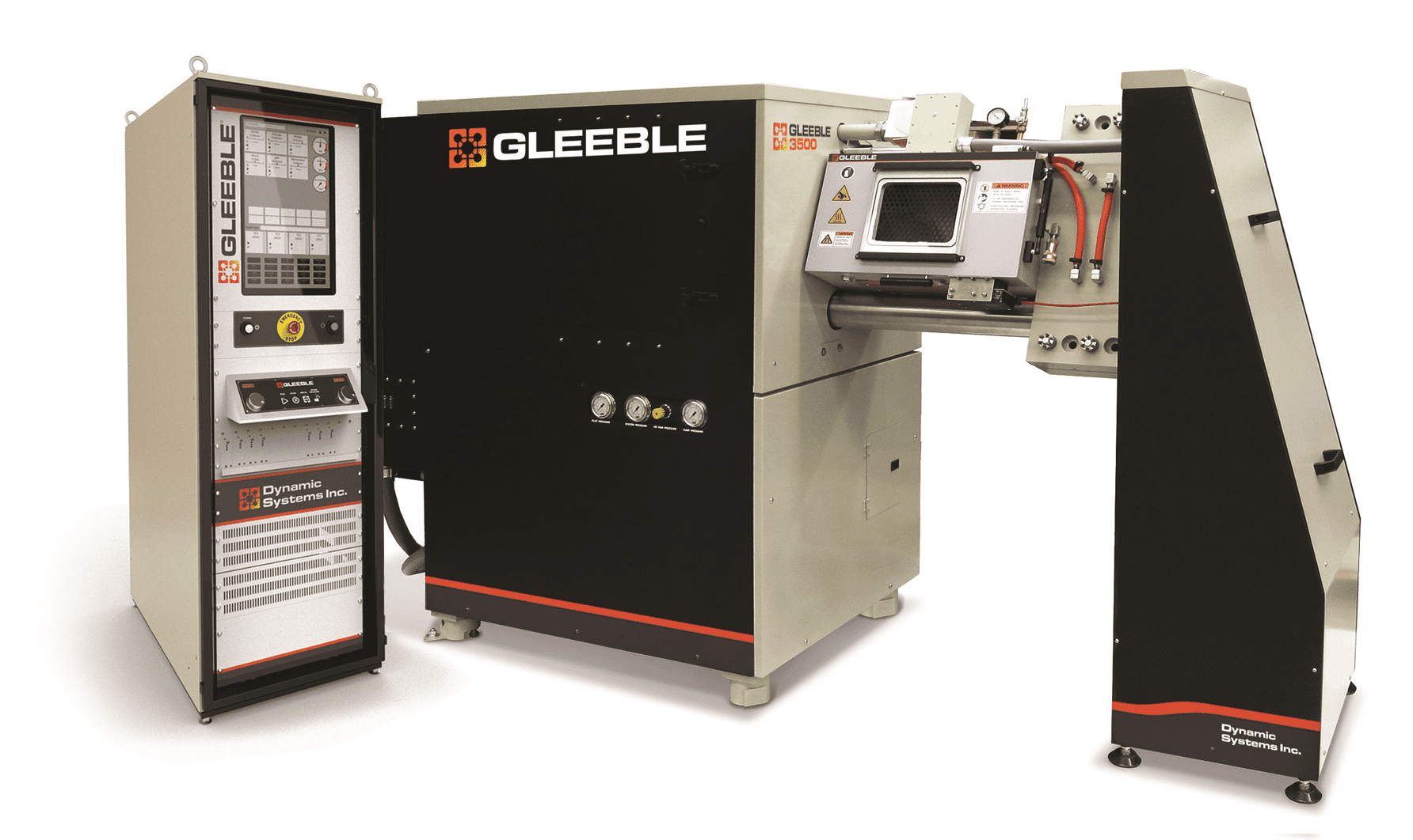
Fig. 5.1 Gleeble 3500-GTC Pedestal.
The Gleeble 3500-GTC is the industry standard for thermal-mechanical physical simulation. With its high-speed heating and wide range of mechanical capabilities, the Gleeble 3500-GTC is ideal for weld HAZ simulations, nil-strength, thermal cycles, heat treatment studies, low-force tests, hot tensile tests, high-speed compression, multi-hit hot deformation tests, melting, solidification, and strip annealing simulations.
Unmatched Customization
A Gleeble 3500 system can be customized to meet a researcher’s needs. The base model, a Gleeble 3500-GTC Pedestal, is built with an integrated vacuum tank and cannot accept Mobile Conversion Units (MCUs). A Gleeble 3500C-GTC is configured similar to a Gleeble 3800. The 3500C-GTC system retains its modularity by accepting Mobile Conversion Units. Most MCUs offered by Dynamic Systems Inc. can be used on this system.
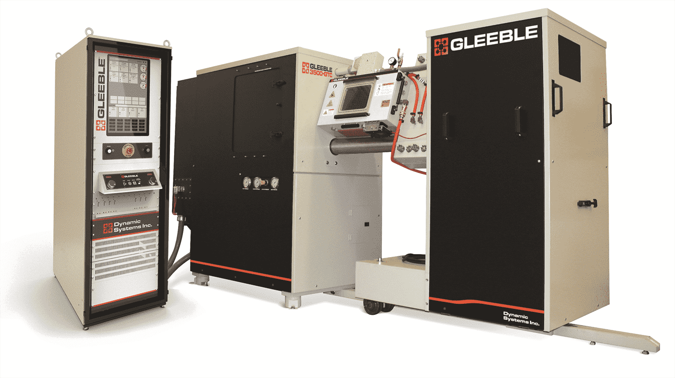
Fig. 5.2 Gleeble 3500C-GTC with MCU.
Advanced Power Options
Further customization of a Gleeble 3500 system is possible through the selection of the hydraulic servo valve assembly. A Gleeble 3500 can be configured with a single 60 gpm valve or a dual valve system. The dual valve configuration, also known as a Gleeble 3500 High-Speed system, consists of one 10 gpm servo valve and one 100 gpm valve. The dual valve configuration offers an impressive combination of high-speed, high force movements with low speed and low-force control.
Material Testing Capabilities of the Gleeble 3500-GTC
|
|
Gleeble systems are supplied with all necessary components for immediate set-up and operation. The digital closed-loop thermal-mechanical control system and software are thoroughly tested prior to any system leaving the factory floor. A wide variety of options and accessories are available to tailor the machine to specific applications.
Gleeble 3500-GTC Pedestal
| Part Number | Description | Sold As |
|---|---|---|
| 3500-10/1-75 | Gleeble 3500-GTC - Pedestal | System |
| 3500-10/1HS-75 | Gleeble 3500-GTC - High-Speed, Pedestal | System |
| 3500-TS-75 | Gleeble 3500-GTC - Thermal Only System | System |
| 35013 | Gleeble 3500-GTC - Pedestal to MCU Upgrade | Kit |
Gleeble 3500C-GTC with Mobile Conversion Unit
| Part Number | Description | Sold As |
|---|---|---|
| 3500C-10/1-75 | Gleeble 3500-GTC - with General-Purpose MCU | System |
| 3500C-10/1HS-75 | Gleeble 3500-GTC - High-Speed, with General-Purpose MCU | System |
5.1. Hydro-Mechanical
Every Gleeble system derives its power from a servo-controlled hydraulic system. The capabilities of the hydro-mechanical system will vary based on Gleeble options.
| Characteristic | Specification |
|---|---|
| Test Frame | Horizontal type with dual 99 mm (3.9 in) diameter columns |
| Mechanical System | Closed-loop hydraulic servo control |
| Data Acquisition Channels | User selectable, up to 16 channels simultaneously, 18-bit ADC |
| Data Sampling Rate | User selectable, up to 50 kHz. |
| Maximum Static Force in Compression | 10,000 kgf (~ 22,000 lbf) (98 kN) |
| Maximum Static Force in Tension | 10,000 kgf (~ 22,000 lbf) (98 kN) |
| Maximum Force Continuously Reversing (Fatigue Rating) | ±5,000 kgf (±11,023 lbf) (±49 kN) |
| Maximum Stroke Rate (no load) | 1,000 mm/s (39.36 in/s) in tension or compression |
| Minimum Stroke Rate | 0.001 mm/s (3.93-5 in/s) in tension or compression |
| Maximum Stroke Distance | 125 mm (4.92 in) |
| Maximum Number of Compression Hits | No Specific Limit |
Note
Maximum stroke distance may be limited by certain jaw configurations.
Note
The total number of compression hits possible is dependent upon many test characteristics. These include the number of deformations, the initial position of the hydraulic stroke, and time between deformations.
Note
Accuracy is measured at a temperature of 23°C (73°F). Maximum stroke rates are at a hydraulic pressure of 203 bar (2,950 psi) ±3 % and an oil temperature of 30°C (86°F).
Maximum Dynamic Force
The maximum dynamic force for the Gleeble 3500 is based on the following graph. For a given stroke speed the hydraulic system will provide a corresponding force. All performance figures for the system are based on operating within the recommended operating region below the Force vs. Stroke curve. The specifications are not valid for tests conducted outside this operating range.
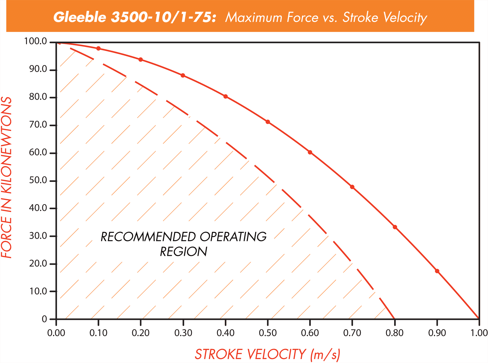
Fig. 5.3 Force vs. Stroke Velocity Gleeble 3500.
Maximum Dynamic Force - High-Speed
The maximum dynamic force for the Gleeble 3500 High-Speed is based on the following graph. For a given stroke speed the hydraulic system will provide a corresponding force. All performance figures for the system are based on operating within the recommended operating region below the Force vs. Stroke curve. The specifications are not valid for tests conducted outside this operating range.
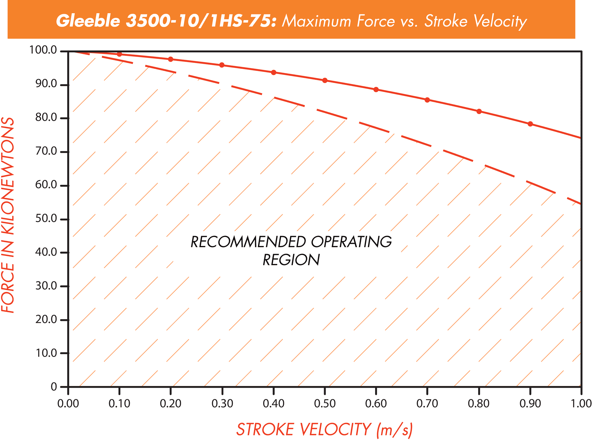
Fig. 5.4 Force vs. Stroke Velocity Gleeble 3500 High-Speed.
Hydraulic Servo Response
The graphs below shows the time and distance required for the piston to reach the programmed rate for a 60 gpm and 100 gpm servo valve respectively.
3500C-10/1-75
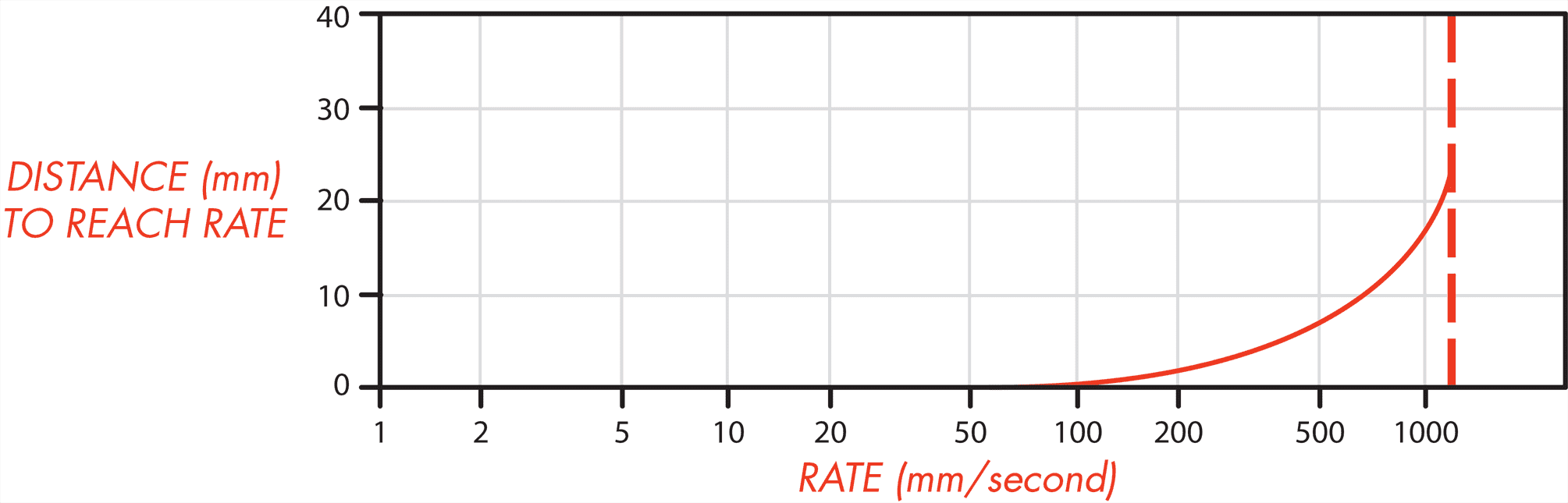
Fig. 5.5 Distance to achieve programmed rate.
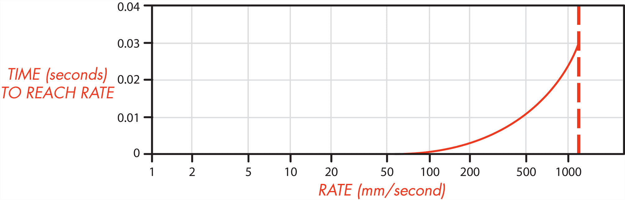
Fig. 5.6 Time to achieve programmed rate.
3500C-10/1HS-75
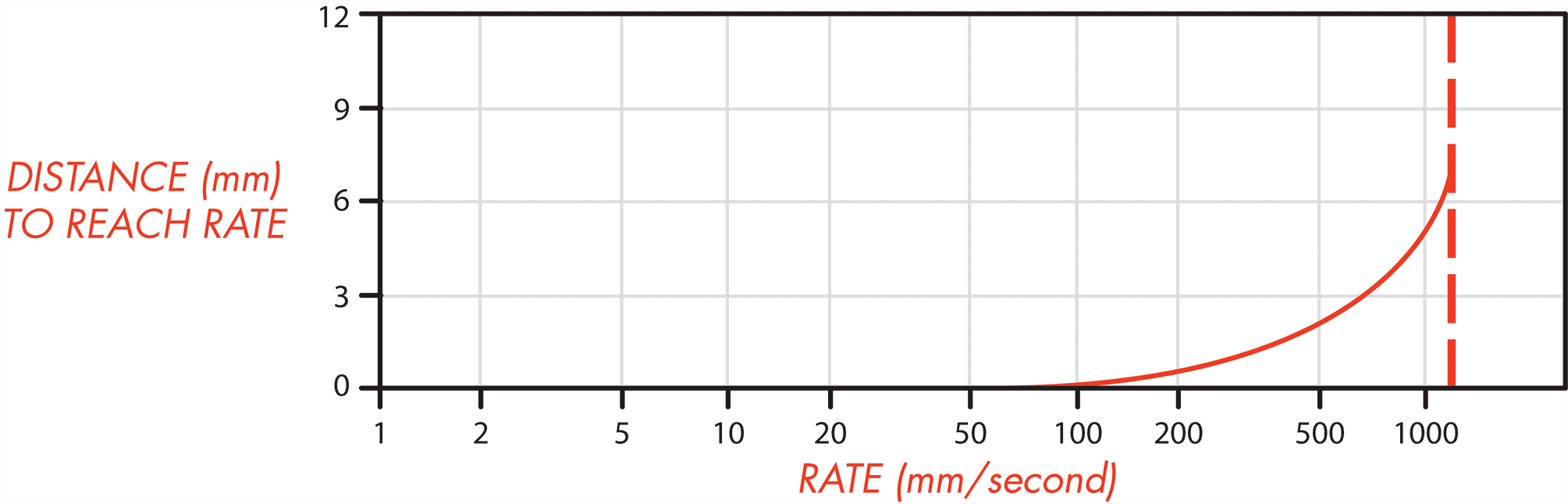
Fig. 5.7 Distance to achieve programmed rate.
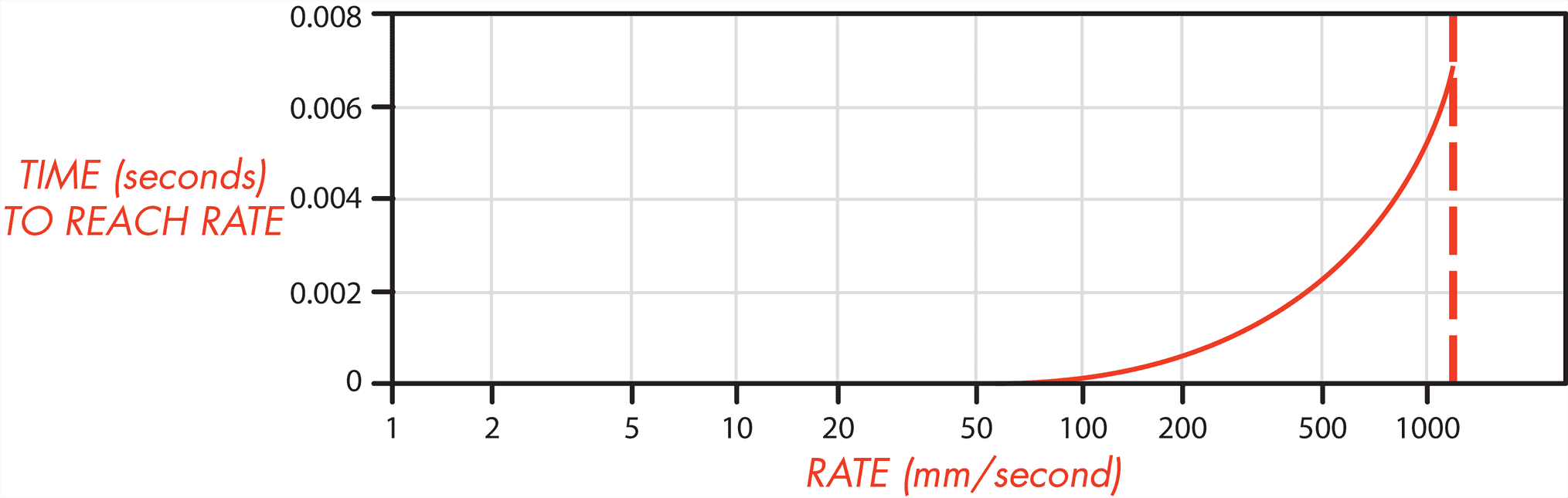
Fig. 5.8 Time to achieve programmed rate.
Limits of High-Speed Testing
While the high-speed servo-systems provide the capability for high-speed compression and tension testing, there are certain limitations in the overall system which must be observed.
For all types of operation the Stroke Rate and Force must be within the operating range as described in the Maximum Force vs. Stroke graph.
For constant Strain Rate programs the duration of the deformation for each hit must be ten times the rated response time of the hydraulic servo valve. The Gleeble system uses high-speed valves with a rated response time of 0.006 seconds. Therefore the duration of the actual deformation of the material during the hit must be equal to or greater than 0.060 seconds.
Load Cell
| Characteristic | Specification |
|---|---|
| Non-linearity | ±0.1 % of full scale |
| Hysteresis | ±0.08 % of full scale |
| Non-Repeatability (Maximum) | ±0.03 % of full scale |
| Overload Rating | 150 % of capacity |
| Deflection - Full Scale | 0.076 mm (0.003 in) |
| Force Measurement Accuracy | ±1.0 % of full scale |
| Force Measurement Resolution | ±1 kgf (2.2 lbf) |
Note
Accuracy is measured at a temperature of 23°C (73°F). Maximum stroke rates are at a hydraulic pressure of 203 bar (2,950 psi) ±3 % and an oil temperature of 30°C (86°F).
Stroke Transducer
| Characteristic | Specification |
|---|---|
| Type | LVDT |
| Linear Range | ±62.5 mm (±2.5 in) |
| Non-Linearity | ±0.25 % of full scale |
| Stroke Measurement Accuracy | ±0.5 % of full scale |
| Stroke Measurement Resolution | 0.002 mm (7.87 x 10⁻⁵ in) |
Note
The Stroke range on a Gleeble 3500 is limited to ±60 mm.
Note
Accuracy is measured at a temperature of 23°C (73°F). Maximum stroke rates are at a hydraulic pressure of 203 bar (2,950 psi) ±3 % and an oil temperature of 30°C (86°F).
5.2. Thermal Subsystems
All Gleeble systems offer a high-speed thermal system with industry-leading performance. Gleeble 3500 and 3800 systems can heat a specimen using an integrated, direct resistance heating system or an optional induction heating system.
Direct resistance heating provides the ability to reproduce the wide variety of thermal profiles that materials undergo in actual processes. This is critical to the success of thermal-mechanical testing and physical simulation. All Gleeble systems have high-speed heating and cooling rates that can accurately replicate nearly any thermal profile required.
Induction heating is well-suited for use in uniaxial compression testing where it can provide a uniform temperature across the specimen from anvil to anvil. Induction heating can also be used in tensile testing, heat treating applications, and plane strain compression testing. Induction heating is also compatible for custom test setups due to the flexibility it offers.
The integration of the Gleeble Induction Heating System does not impact the functionality of the direct resistance heating capabilities. The Induction Heating System retains the performance standards researchers have come to know and expect from their Gleeble systems. Choosing between standard direct resistance heating and optional induction heating is available through the configuration mode of a GTC system. Only one heating method can be used per test.
| Characteristic | Specification |
|---|---|
| Primary Heating System Type and Control | Direct resistance with closed-loop control |
| Optional Heating System Type and Control | Gleeble Induction Heating System (IHS) with closed-loop control |
| Temperature Controller | Digital closed-loop control using 18-bit ADC and 32-bit digital processor |
| Temperature Range | -150°C to 3,000°C (-238°C to 5,432°F) |
| Response Rate | 10,000°C/s (18,000°F/s) |
| Temperature Monitoring Source | Thermocouple or Optional Pyrometer Control Cameras |
| Thermocouple Sampling Rate | Twice the power line frequency (100 - 120 Hz) |
| Resolution | ±1°C or°F |
| Maximum Number Of Simultaneous Thermal Channels | 4 thermocouple channels, or 2 thermocouple channels and 1 pyrometer channel |
| Accuracy of Control | ±1°C (in steady state) |
| Accuracy of Measurement | ±2°C or ±1 % of temperature (whichever is greater) plus the accuracy of the thermocouple wire (in steady state) |
Note
An optional Pyrometer Control Camera is required for temperatures above 2,100°C (3,812°F). An optional Cryogenic Quench System kit is required for temperatures below room temperature.
Note
As the specimen size, diameter, length, or cross-sectional area increases the effective heating rate will decrease.
5.2.1. Thermocouple Wire Types
Gleeble systems are capable of recording specimen temperature with various thermocouple wire types. The following types of thermocouple wire can be used on any Gleeble system.
| Part Number | TC Type | Material | Sold As |
|---|---|---|---|
| Operating Range: 0 - 1,450°C (32 - 2,642°F) | |||
| TC005 | R- or S- | Pt 100% | Inch |
| TC006 | R+ | Pt 87% - Rh 13% | Inch |
| TC009 | S+ | Pt 90% - Rh 10% | Inch |
| Operating Range: -200 - 1,250°C (-328 - 2,282°F) | |||
| TC014 | K- | Alumel | Spool |
| TC015 | K+ | Chromel | Spool |
| Operating Range: 0 - 1,700°C (32 - 3,092°F) | |||
| TC017 | B- | Pt 94% - Rh 6% | Inch |
| TC018 | B+ | Pt 70% - Rh 30% | Inch |
| Operating Range: 0 - 750°C (32 - 1,382°F) | |||
| TC030 | J+ | Fe 100% | Spool |
| TC031 | J- | Constantan | Spool |
| Operating Range: -200 - 900°C (-328 - 1,652°F) | |||
| TC032A | E+ | Chromega | Spool |
| TC033 | E- | Constantan | Spool |
| Operating Range: 0 - 2,320°C (32 - 4,208°F) | |||
| TC010 | C+ | W 95% - Re 5% | Inch |
| C- | W 74% - Re 26% | ||
Note
TC wire types C, K, J, and E have a nominal wire diameter of 0.254 mm (0.01 in). TC wire types R, S, and B have a nominal wire diameter of 0.2032 mm (0.008 in).
Note
Gleeble systems can support additional thermocouple wire types not shown. Contact Dynamic Systems for additional information regarding the use of alternate thermocouple wire types.
5.2.2. Heating Rates
Heating rates are based on using a 480 V / 200 A power supply, full contact copper grips, and 1018 carbon steel specimens in the General-Purpose Mobile Conversion Unit MCU. See Gleeble Grips for more information regarding the selection of grips.
| Specimen | Free Span | Drawing Number | Maximum Heating Rate |
|---|---|---|---|
| °C/s (°F/s) | |||
| 6 mm dia x 71 mm long | 10 mm | SMR002B | 10,000 (18,000) |
| 10 mm dia x 71 mm long | 10 mm | SMR009B | 1,000 (1,800) |
| 10 mm dia x 15 mm long With non ISO-T Anvils | SMC203B | 50 (90) | |
| 10 mm dia x 15 mm long With ISO-T Anvils | 5 (9) | ||
5.2.3. Cooling Rates
Free Cooling Rates
The Gleeble system is able to control the specimen cooling rate based on conductive heat transfer. The efficiency and maximum rate of conductive cooling is directly impacted by grip and specimen geometry, material, cleanliness, and system’s chilled process fluid flow rate.
The free cooling rates are achieved using full contact copper grips on 1018 carbon steel specimens. See Gleeble Grips for more information regarding the selection of grips.
| Specimen | Free Span | Drawing Number | Temperature Range | Cooling Rate |
|---|---|---|---|---|
| °C (°F) | °C/s (°F/s) | |||
| 6 mm dia x 71 mm long | 10 mm | SMR002B | 950 - 800 (1,742 - 1,472) | 140 (252) |
| 800 - 500 (1,472 - 932) | 78 (140.4) | |||
| 10 mm dia x 84 mm long | 10 mm reduced to 6 mm dia x 6 mm long | SMR202B | 950 - 800 (1,742 - 1,472) | 330 (594) |
| 800 - 500 (1,472 - 932) | 200 (360) | |||
Quench Cooling Rates
Optional quench systems are available which can use compressed air, inert gas, or water to cool the specimen at higher rates than are achievable when relying solely on conduction cooling.
| Specimen | Free Span | Drawing Number | Temperature Range | Rate |
|---|---|---|---|---|
| °C (°F) | °C/s (°F/s) | |||
| 1 mm thick x 10 mm wide x 100 mm long | 25 mm | SMF002B | 1,000 - 600 (1,832 - 1,112) | 10,000 (18,000) |
| 6 mm dia x 86 mm long | 25 mm | SMR005B | 1,000 - 600 (1,832 - 1,112) | 2,000 (3,600) |
Note
The cooling rates are achieved using full contact copper grips on 1018 carbon steel specimens quenched with water. See Gleeble Grips for more information regarding the selection of grips.
5.2.4. Temperature Uniformity Within the Specimen
The Gleeble system has the unique ability to control the temperature uniformity and thus the thermal gradient within the test specimen. Tests can be performed with very uniform temperature within the specimen work zone, equivalent to a furnace-based test, or with the large thermal gradients needed to accurately simulate welding and other processes.
When using Joule heating, the current density in a Gleeble specimen is uniformly distributed across the entire specimen cross-sectional area, meaning that the Gleeble is able to heat the entire specimen simultaneously, from surface to center. Since the Gleeble grips are cool, the heat generated in the specimen will diffuse into the grips, creating a thermal gradient with the ends of the specimen generally being cooler than the center. The severity of the steady state thermal gradient is defined by the rate of heat generated in the specimen, offset by the heat lost to the grips. This gradient can be controlled by utilizing grips of materials with differing thermal and electrical conductivity and contact area. Thermally and electrically conductive grips with a large specimen contact area will be kept cold more readily with the water-cooled jaws, and will accept significant heat from the specimen, resulting in “cold ends” and a very steep thermal gradient.
Grips with smaller contact area and higher thermal resistance will pull much less heat from the specimen. Grips manufactured from material with higher electrical resistance will, themselves, heat under the same current that is heating the specimen. These factors will result in very little heat being pulled from the specimen and a very flat thermal gradient. In some cases the grips or anvils holding the specimen may reach temperatures equal to or higher than the specimen, creating a “reverse” thermal gradient.
When considering Gleeble thermal gradients, it is also critical to differentiate between the axial thermal gradient (along the length of the specimen), and the transverse thermal gradient (across the diameter or cross section of the specimen). Even in situations where a specimen experiences a very high axial thermal gradient, the transverse, or crosswise thermal gradient will be very small. This ability to generate isothermal planes is a critical benefit of the Gleeble. In contrast to furnace or induction heating methods, where the specimen can only be heated on the surface or to a limited “skin depth”, the center of a Gleeble specimen is heated at the same rate as the surface regardless of the heating rate. This ability to generate isothermal planes allows for the Gleeble platform to perform dilatometry and welding heat affected zone experiments at heating and cooling rates relevant to welding and other processes on specimens that are large enough for subsequent mechanical property or toughness testing. This is not feasible on furnace or inductively-heated systems that rely on thermal conduction to heat the center of the specimen. Axial thermal uniformity within a specimen is reported as the difference between the specimen’s center to edge thermal measurements and is dependent upon:
|
|
The following data was obtained using Stainless Steel partial contact grips on 1018 carbon steel specimens. Measurements are taken at steady state temperatures. See Gleeble Grips for more information regarding the selection of grips.
| Specimen | Free Span | Drawing Number | Temperature Uniformity |
|---|---|---|---|
| Lengthwise Thermal Gradient | |||
| 10 mm dia x 111 mm long | 50 mm | SMR023B | ±0.5% of Tavg for 7 mm of midspan |
| Crosswise Thermal Gradient | |||
| 10 mm dia x 86 mm long | 25 mm | SMR012B | ±0.5% of Tavg |
Note
Tavg is the average of the specimen cross section temperature at 1,000°C (1,832°F).
Reproducibility
Thermal gradients in resistance-heated specimens are dependent upon on the properties of the specimen. All specimens with the same physical, mechanical, electrical, and chemical properties will have the same gradients within the accuracy of the thermal system, provided that the specimen grips are in good condition.
5.3. Specimen Size Considerations
Gleeble systems are capable of testing a wide variety of material compositions and specimen geometries. Inherent limitations of the system, such as distance between the jaw or anvil faces, the maximum or minimum stroke speed, test temperature, and force limitations for the individual system must be considered when selecting a specific specimen geometry.
The target temperature of a test will also impact the size of a specimen that can safely be tested with a Gleeble system. For example, when considering a standard uniaxial compression specimen, it is possible for a soft material such as aluminum or copper to be tested at ambient temperature. Harder materials, such as steel or titanium alloys, are expected to be tested at elevated temperatures.
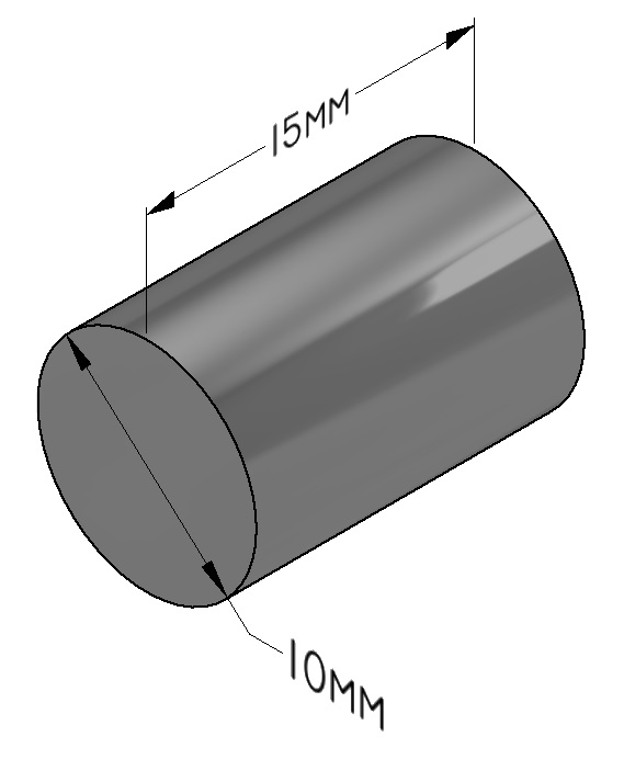
Fig. 5.9 Uniaxial Compression Specimen - SMC203.
The Gleeble 3500 and 3800’s vacuum tank configuration limits the maximum and minimum specimen geometry that can be tested. Due to the modularity of the Gleeble systems, the possible specimen geometries can rage from a 260 mm long strip specimen to a 10 mm long compression specimen. When configured with the General-Purpose MCU’s Pocket Jaws or the Gleeble 3500 Pedestal’s Pocket Jaws, a specimen with a maximum free span of 120 mm can be tested.
Specimen geometry will vary with any specific test. DSI has identified recommended specimen geometries for commonly performed simulation tests. Contact Dynamic Systems for assistance identifying a recommended specimen geometry as needed.
| Popular Specimen Sizes | |||
|---|---|---|---|
| Specimen Length | Specimen Width | Specimen Thickness | Drawing Number |
| Bar Specimens | |||
| 116.5 mm | 10 mm dia | N/A | SMR111 |
| 121.5 mm | 10 mm dia | N/A | SMR112 |
| 71 mm | 6 mm dia | N/A | SMR002 |
| 71 mm | 11 mm Sq | N/A | SMS006 |
| Flat Specimens | |||
| 100 mm | 10 mm | 1 mm | SMF002 |
| Uniaxial Compression | |||
| 9 mm | 6 mm dia | N/A | SMC206 |
| 12 mm | 8 mm dia | N/A | SMC200 |
| 15 mm | 10 mm dia | N/A | SMC203 |
| Plane Strain | |||
| 20 mm | 15 mm | 10 mm | SMC001 |
| 35 mm | 25 mm | 15 mm | SMC007 |
To achieve the best thermal control, flat specimens should have a cross-sectional area between 25 mm2 and 400 mm2 (0.0387 in2 and 0.620 in2).
Note
To test highly conductive specimens, additional grounding blocks must be installed on the Gleeble. See Heating Modification for a Highly Conductive Specimen for more information. The use of hot grips is recommended for highly conductive specimens. See Gleeble Grips for more information regarding the selection of grips.
5.4. Additional Features
Vacuum Tank
One of the distinguishing features of a Gleeble system is the ability to test materials in a controlled atmosphere. Researchers can simulate processes and test specimens in standard atmosphere, in rough vacuum, in high vacuum or in an inert gas environment. This environmental control is possible due to the large vacuum tank, also referred to as a “test chamber,” that is incorporated into every Gleeble. The vacuum tank is fully integrated into the Gleeble system and can be controlled with manual controls or through software controls. A popular approach to atmosphere control in the Gleeble includes “washing cycles” which involve pumping down to a rough vacuum in the tank and then backfilling with an inert gas. This can be conducted multiple times to ensure that the desired atmosphere is achieved.
Most Gleeble vacuum tanks include viewing ports, typically incorporated into the tank doors to allow visual observation of simulations. In some cases, viewing windows are removed or covered to protect users from the light intensity of specimens at elevated temperatures. Depending on the Gleeble model, vacuum tanks may include one or two doors with viewing windows as well as additional ports for measurement devices or equipment feedthroughs.
Feedthroughs are an important feature in the Gleeble vacuum tanks. They allow researchers to install equipment that can measure or interact with the specimen during a test while still controlling the atmosphere. For example, vacuum-sealed electrical feedthroughs allow communication with transducers such as thermocouples, load cells, and strain transducers. Piping feedthroughs enable atmosphere control (e.g. inert gas backfill and vacuum supply) as well as allowing quenching media to be utilized.
Warning
The Gleeble vacuum tank is designed to operate under vacuum or atmospheric pressure, with either air or an inert gas surrounding the specimen. Positive atmospheric pressure, explosive, flammable or corrosive gases, or any mixtures of these gases, should never be used as part of the vacuum tank atmosphere.
Air Ram
The air ram is designed to maintain a constant force on the specimen in either tension or compression. When properly used it can simplify many Gleeble tests and increase the versatility of the Gleeble system.
The air ram system consists of twin air pressure cylinders connected to the moving jaw of the Gleeble. The same compressed air source used for the rest of the Gleeble system supplies the air ram. The air ram can be activated automatically during a Gleeble test or manually by a button on the HMI. Additional controls are provided for selecting compression or tension, and the pressure (force) applied to the specimen. The maximum force of the air ram is 450 kgf (992 lbf) at 5.6 kg/cm 2 (80 psi) Gleeble air supply pressure.
The following are some typical applications of the air ram:
- Resistance Butt Welding:
- To prevent arcing across the specimen interface, a compressive force is applied prior to heating in order to keep the two faces of the specimen in contact.
- Hot Rolling:
- A compressive force is applied to hold the specimen between the anvils prior to heating and during subsequent deformation.
- Continuous Strip Annealing:
- To compensate for thermal expansion, a small tensile force is maintained during the test in order to move the jaw and keep the strip specimen from bowing.
Hydraulic Power Unit
Gleeble 3500 and 3800 systems are equipped with an independent hydraulic power unit (HPU). The HPU is the primary source of mechanical motion for these Gleeble systems. The HPU is capable of regulating the output pressure of the hydraulic fluid based on the Gleeble system configuration.
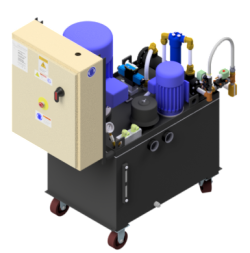
Fig. 5.10 Gleeble Hydraulic Power Unit.
Typical Gleeble configurations allow the user to choose between a high and low output pressure. The pressure can be manually selected with a button on the HMI (Human-Machine Interface) or through the programming of a Gleeble test.
Special configurations of the Gleeble will limit the pressures available for testing. When a low-force load cell is installed, the Gleeble will automatically limit the HPU output to a low pressure. Users will not be able to select a higher hydraulic pressure. With a Hot Torsion MCU installed, the Gleeble will automatically reduce the high pressure output to to an intermediate pressure. The user can select between the standard low pressure or the newly reduced high pressure.
Note
Reference Hydraulic Oil for common service parts.
The Gleeble HPU uses the same process fluid chiller as the Gleeble system to enable automatic control of the hydraulic oil temperature. By automatically regulating the temperature of the hydraulic oil, the Gleeble is capable of maintaining peak performance in a variety of temperature environments. The HPU is protected by sensors that detect high oil temperature, and high or low oil level.
| Characteristic | Specification | |
|---|---|---|
| Pump Motor | 20 hp | |
| Variable Pressure Output | Low Pressure | 68.94 bar (1000 psi) |
| Intermediate Pressure | 137.89 bar (2000 psi) | |
| High Pressure | 206.84 bar (3000 psi) | |
| Hydraulic Oil Reservoir Capacity | 170 L (45 gal) | |
Hydraulic Pump Sound Damping Enclosure
The 35343 Hydraulic Pump Sound Damping Enclosure is designed for locations where additional noise reduction is required at the pump installation site.
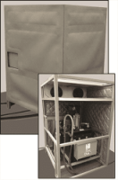
Fig. 5.11 Hydraulic Power Unit Sound Damping Enclosure - DSI# 35343.
This acoustic enclosure consists of quilted material barrier panels with a quilted material roof. These panels are hung on a frame mounted to the hydraulic pump. A typical Gleeble 3500 or 3800 hydraulic power unit, without a sound damping enclosure, produces 86 to 90 dBA, depending on the surroundings and mounting position. HPUs with the sound damping enclosure produce 67 to 70 dBA.
The 35343 Hydraulic Pump Sound Damping Enclosure includes the following:
- Four-sided sound damping enclosure with a roof
- One (1) 254 mm (10 in) x 254 mm (10 in) viewing window
- Exhaust fan for cooling which is powered from the hydraulic pump
The approximate size of the enclosure is 1.524 m (60 in) long x 1.117 m (44 in) wide x 1.879 m (74 in) high. The enclosure will only accommodate the currently supplied 20 hp HPU. This enclosure is portable allowing removal of the panels for maintenance and service. Installation and assembly is required, and available at an additional cost.
| Part Number | Description | Sold As |
|---|---|---|
| 35343 | Sound Damping Enclosure for 20 hp Hydraulic Power Unit | Ea |
5.5. Gleeble Physical Dimensions
| Equipment | Height | Depth | Width | Weight |
|---|---|---|---|---|
| Control Console | 180 cm (71 in) | 66 cm (26 in) | 61 cm (24 in) | 195 kg (430 lb) |
| 3800 Load Unit | 160 cm (63 in) | 86 cm (34 in) | 239 cm (94 in) | 1,425 kg (3,143 lb) |
| 3500C Load Unit | 160 cm (63 in) | 86 cm (34 in) | 239 cm (94 in) | 1,425 kg (3,143 lb) |
| 3500 Pedestal Load Unit | 160 cm (63 in) | 86 cm (34 in) | 273 cm (107 in) | 1,732 kg (3,819 lb) |
| Hydraulic Power Unit with Oil | 155 cm (61 in) | 142 cm (56 in) | 74 cm (29 in) | 655 kg (1,444 lb) |
| General-Purpose MCU for 3500C and 3800 | 158 cm (62 in) | 86 cm (34 in) | 157 cm (62 in) | 565 kg (1,245 lb) |
Note
The Hydraulic Power Unit weighs 529 kg (1,168 lb) without oil.
Note
For complete information on all of the MCUs offered by DSI, please see Mobile Conversion Units.
5.5.1. Frame and Machine Stiffness
Frame Stiffness: (includes columns and crossheads)
- 5.02 x 10E-9 m/N
- 8.78 x 10E-7 in/lbf