12. Gleeble Induction Heating System (IHS)
12.1. Induction Heating System
Gleeble systems have historically relied on direct resistance heating to provide extremely fast, uniform and responsive heating. While this method offers considerable advantages over other heating techniques, there are cases where induction heating is preferred. For customers looking to heat via induction, DSI now offers the Induction Heating System (IHS). Developed in partnership with a leading supplier in the induction heating industry, the Gleeble IHS is fully integrated with the Gleeble and allows the user to select either induction or resistance heating for each test. The cooling requirements of the IHS are satisfied through the existing Gleeble cooling loop. It also draws power directly from the Gleeble load unit.
Induction heating is well-suited for use in uniaxial compression testing where it can provide a uniform temperature across the specimen from anvil to anvil. Induction heating can also be used in tensile testing, heat treating applications, and plane strain compression testing. Induction heating is also compatible for custom test setups due to the flexibility it offers.
The integration of the Gleeble Induction Heating System does not impact the functionality of the direct resistance heating capabilities. The Induction Heating System retains the performance standards researchers have come to know and expect from their Gleeble systems. Choosing between standard direct resistance heating and optional induction heating is available through the configuration mode of a GTC system. Only one heating method can be used per test.
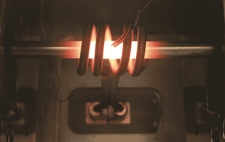
Fig. 12.1 Induction Heating Coil.
| Part Number | Description | Sold As |
|---|---|---|
| 37200 | Induction Heater Option - Factory Built 3500 or 3800-GTC | Ea. |
| 37201 | Induction Heater Option - Series 3 System Equipped with GTC Control - Retrofit | Ea. |
| Required Accessories | ||
| 59025 | Accessory Instrument Module - GTC Systems only | |
Note
Series 3 systems must be upgraded to a GTC system to incorporate the Induction Heating System.
12.2. Induction Requirements
| Gleeble Induction Equipment Input | |
|---|---|
| Model | 15 kW |
| AC Voltage | 360 - 520 Vrms |
| Frequency | 50 - 60 Hz |
| AC Line Power | 17 kVA max |
| Power Factor | 0.92 |
| Gleeble Induction Equipment Output | |
|---|---|
| Frequency | 50 - 150 kHz |
| Voltage | 500 Vrms |
| Power | 15 kW |
| Efficiency (line-coil) | > 90 % |
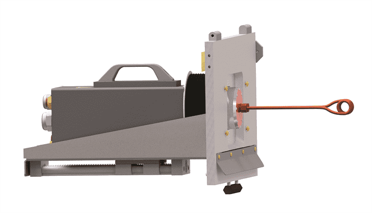
Fig. 12.2 Induction Heating Work Head.
| Gleeble Induction Equipment Operating Requirements | |
|---|---|
| Ambient Temperature | 4 - 45°C (39 - 113°F) |
| Coolant Temperature | 20 - 35°C (68 - 95°F) |
| Coolant Flow | 10.4 L/min (2.74 gal/min) |
| Coolant Composition | 30 - 50% Propylene Glycol |
| Gleeble Induction System Performance | |
|---|---|
| Temperature Range | Room Temperature to 1,700°C |
| Thermocouple Sampling Rate | Twice the Power Supply Frequency (100 - 120 Hz) |
| Resolution | ±1 (°C or°F) |
| Accuracy of Control | ±1°C (steady state) |
| Accuracy of Measurement | ±2°C or ±1 % of temperature (whichever is greater) plus the accuracy of the thermocouple wire (in steady state) |
12.3. Heating Rates
Heating rates are based on 1018 carbon steel uniaxial compression samples at temperatures below the Curie point and held between Si3N4 anvils.
| Specimen | Drawing Number | Maximum Heating Rate |
|---|---|---|
| °C/s (°F/s) | ||
| 6 mm dia x 9 mm long | SMC206B | 15 (27) |
| 10 mm dia x 15 mm long | SMC203B | 15 (27) |
| 15 mm dia x 22 mm long | SMC210B | 15 (27) |
12.4. Cooling Rates
Free Cooling Rates
The Gleeble system is able to control the specimen cooling rate based on conductive heat transfer. The efficiency and maximum rate of conductive cooling is directly impacted by grip and specimen geometry, material, cleanliness, and system’s chilled process fluid flow rate.
The maximum cooling rates listed below are average rates for 1018 carbon steel uniaxial compression specimens, held between Si3N4 anvils, and in a rough vacuum atmosphere.
| Specimen | Drawing Number | Temperature Range | Cooling Rate |
|---|---|---|---|
| °C (°F) | °C/s (°F/s) | ||
| 6 mm dia x 9 mm long | SMC206B | 1,000 - 500 (1,832 - 932) | 25 (45) |
| 10 mm dia x 15 mm long | SMC203B | 1,000 - 500 (1,832 - 932) | 5 (9) |
| 15 mm dia x 22 mm long | SMC210B | 1,000 - 500 (1,832 - 932) | 2 (1.1) |
Quench Cooling Rates
Refer to Quench Kits for optional quench systems that are available. All quench systems can use compressed air or inert gas to cool the specimen at high rates. A mixture of compressed air and water can also be used in the quench systems for even higher cooling rates.
Air Quenching Rates
Maximum cooling rates listed below are average rates for 1018 carbon steel specimens, held between Si3N4 anvils, and air quenched using a Quench Tank and Multi-Function Open Quench Spray Nozzle Kit with a maximum of 8.2 bar (120 psi) available air pressure. See Quench Systems for more information about quench kits and quench tanks.
| Specimen | Drawing Number | Cooling Rate |
|---|---|---|
| °C/s (°F/s) | ||
| 6 mm dia x 9 mm long | SMC206B | 250 (450) |
| 10 mm dia x 15 mm long | SMC203B | 40 (72) |
Water Quenching Rates
Maximum cooling rates listed below are average rates for 1018 carbon steel specimens, held between Si3N4 anvils, and water quenched using a Quench Tank and Multi-Function Open Quench Spray Nozzle Kit with a maximum of 8.2 bar (120 psi) available air pressure. See Quench Systems for more information about quench kits and quench tanks.
| Specimen | Drawing Number | Temperature Range | Cooling Rate |
|---|---|---|---|
| °C (°F) | °C/s (°F/s) | ||
| 6 mm dia x 9 mm long | SMC206B | 1,000 - 300 (1,832 - 572) | 500 (900) |
| 10 mm dia x 15 mm long | SMC203B | 1,000 - 300 (1,832 - 572) | 350 (630) |
12.5. Temperature Uniformity Within The Specimen
Temperature uniformity within the specimen is highly dependent on multiple factors, including sample geometry, coil geometry, sample material, and anvil material.
Tests were performed using 1018 carbon steel uniaxial compression specimens, quartz anvils, and the HTR5006 induction coil. Temperature was measured at the center of the sample and 1 mm from each end of the sample. Gradient is reported as the difference from the center measurement to the edge measurement.
| Specimen | Drawing Number | Surface Thermal Gradient |
|---|---|---|
| 6 mm dia x 9 mm long | SMC206B | ±30°C (86°F) |
| 10 mm dia x 15 mm long | SMC203B | ±10°C (50°F) |
| 15 mm dia x 22 mm long | SMC210B | ±30°C (86°F) |
12.5.1. Reproducibility
Thermal gradients in resistance and induction-heated specimens are based on the properties of the specimen material being heated. Thermal gradients in induction systems are also influenced by heating coil geometry. All specimens with the same physical, mechanical, electrical and chemical properties will have the same gradients, within the accuracy of the control system, provided that the specimen grips, anvils, and induction coils are in good condition and properly aligned.
12.6. Specimens
The Gleeble Induction Heating System (IHS) can be used in testing all typical Gleeble specimen sizes. However, as with direct resistance heating, induction heating rates, cooling rates, and thermal gradients are highly dependent on material properties, sample geometry and experimental setup. Larger specimens will decrease heating and cooling rates, and may reduce the maximum allowable temperature or time at temperature. Higher temperatures may be possible with smaller or specially designed specimens and custom induction coils. Damage caused by the use of non-recommended sample sizes, temperatures, or testing times will not be covered under the warranty.
12.7. Compression Kits
In order to account for the extended anvil length for use with the Induction Heating System, compression anvil base assemblies have been specially modified for use in the Hydrawedge II MCU and the Compression Test Adapter. General-Purpose MCU anvil bases can be used for Induction and Resistive based heating methods. When preforming any compression testing with the Induction Heating System, induction based anvils must be used.
12.7.1. Uniaxial Compression - Induction Anvil Bases
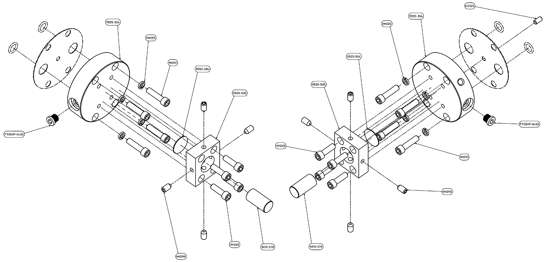
Fig. 12.3 Hydrawedge II Mounted - ISO-T Flow Stress Anvil Assembly - Induction Heating System - DSI# 9555-006.
| Part Number | Description | Sold As |
|---|---|---|
| 9555-006 | ISO-T Uniaxial Compression Anvil Assembly - Hydrawedge II MCU or Compression Test Adapter - only used with the Induction Heating System | Kit |
| 9555-100 | ISO-T Uniaxial Compression Anvil Assembly - General-Purpose MCU Pocket Jaws - Requires Induction Specific Anvils when used with the Induction Heating System |
12.7.1.1. Uniaxial Compression - Induction Anvils
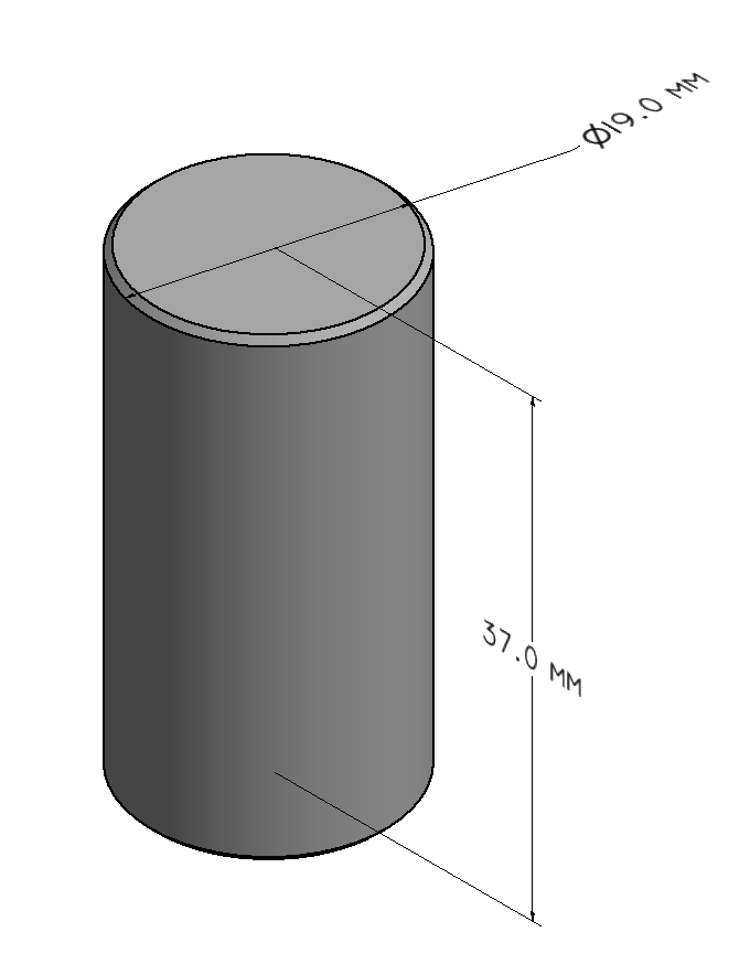
Fig. 12.4 Uniaxial Compression Anvil - Silicon Nitride - DSI# 9219-378.
| Part Number | Description | Sold As |
|---|---|---|
| 9219-375S | Uniaxial Compression Anvil - Quartz - 19.1 mm dia x 37 mm long (0.748 in dia x 1.456 in long) - Induction Heating System only | Ea. |
| 9219-378 | Uniaxial Compression Anvil - Silicon Nitride - 19.1 mm dia x 37 mm long (0.748 in dia x 1.456 in long) - Induction Heating System only | Ea. |
12.7.2. Small Plane Strain - Induction Anvil Bases
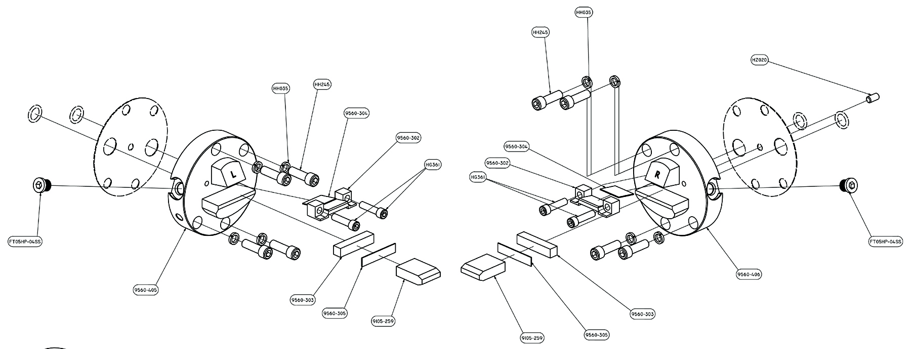
Fig. 12.5 Hydrawedge II Mounted - Small Plane Strain - Induction Heating System - DSI# 9560-112.
| Part Number | Description | Sold As |
|---|---|---|
| 9560-112 | Small Plane Stain Anvil Base Assembly - Hydrawedge II Mounted - only used with the Induction Heating System | Kit |
| 9560-113 | Small Plane Stain Anvil Base Assembly - Compression Test Adapter Mounted - only used with the Induction Heating System | Kit |
| 9560-001 | Small Plane Strain Anvil Base Assembly - General-Purpose MCU Pocket Jaws - Requires Induction Specific Anvils when used with the Induction Heating System |
12.7.2.1. Small Plane Strain - Induction Anvils
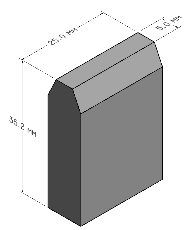
Fig. 12.6 Extended Small Plane Strain Anvil - Silicon Nitride - DSI# 9105-259.
| Part Number | Description | Sold As |
|---|---|---|
| 9105-259 | Extended Small Plane Strain Anvil - Silicon Nitride - 5 x 25 x 20 mm (0.196 x 0.984 x 0.787 in) - Induction Heating System only | Ea. |
| 9105-300 | Extended Small Plane Strain Anvil - Quartz - 5 x 25 x 20 mm (0.196 x 0.984 x 0.787 in) - Induction Heating System only | Ea. |
12.7.3. Large Plane Strain - Induction Anvil Bases
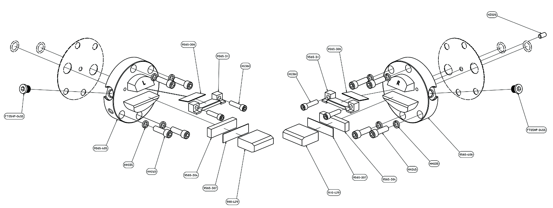
Fig. 12.7 Hydrawedge II Mounted - Large Plane Strain - Induction Heating System - DSI# 9565-110.
| Part Number | Description | Sold As |
|---|---|---|
| 9565-110 | Large Plane Stain Anvil Base Assembly - Hydrawedge II Mounted - only used with the Induction Heating System | Kit |
| 9565-111 | Large Plane Stain Anvil Base Assembly - Compression Test Adapter Mounted - only used with the Induction Heating System | Kit |
12.7.3.1. Large Plane Strain -Induction Anvils
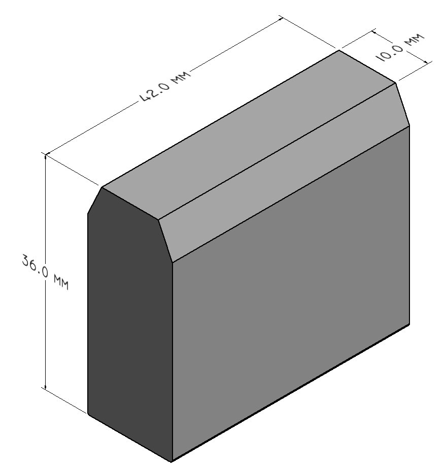
Fig. 12.8 Extended Large Plane Strain Anvil - Silicon Nitride - DSI# 9110-429.
| Part Number | Description | Sold As |
|---|---|---|
| 9110-429 | Extended Large Plane Strain Anvil - Silicon Nitride - 10 x 42 x 36 mm (0.393 x 1.653 x 1.417 in) - Induction Heating System only | Ea. |
| 9110-430 | Extended Large Plane Strain Anvil - Quartz 10 x 42 x 36 mm - (0.393 x 1.653 x 1.417 in) - Induction Heating System only | Ea. |
12.8. Quenching Kits
12.8.1. Induction Heating System Quench Kits
12.8.1.1. Multi-Function Open Quench Spray Nozzle Kit
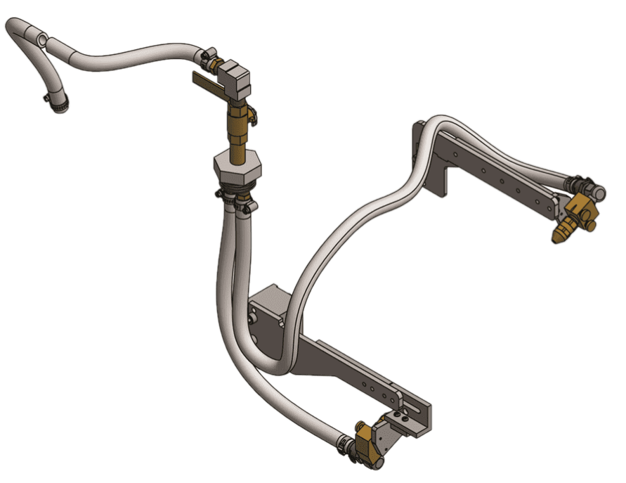
Fig. 12.9 Multi-Function Open Quench Spray Nozzle Kit - DSI# 31733.
The 31733 Multi-Function Open Quench Spray Nozzle Kit features a surface quenching design with sprayer nozzles that quench the specimen by direct contact with the quenching medium. The spray heads are mounted outside the Gleeble’s Pocket Jaws, above and below the test specimen. When the Multi-Function Quench Spray Nozzles are used, the quenching medium is sprayed directly on the specimen. If the Gleeble is equipped with a vacuum system, the vacuum is turned off to prevent the quench medium from contaminating the vacuum pump.
This quench spray nozzle kit can be used on the Pocket Jaws of the General-Purpose Mobile Conversion Unit MCU, the Low-Force Pocket Jaws for the Gleeble 3500 and 3800, the Compression Test Adapter, and with the Gleeble Induction Heating System (IHS).
| Part Number | Description | Sold As |
|---|---|---|
| 31733 | Multi-Function Open Quench Spray Nozzle Kit | Kit |
12.8.1.2. Hydrawedge II - Multi-Function Open Quench Spray Nozzle Kit
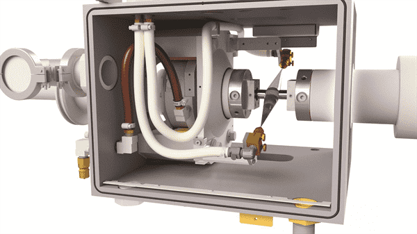
Fig. 12.10 Multi-Function Open Quench Spray Nozzle Kit - Hydrawedge II - DSI# 31735.
The 31735 Hydrawedge II - Multi-Function Open Quench Spray Nozzle Kit features a surface quenching design with sprayer nozzles that quench the specimen by direct contact with the quenching medium. The spray heads are mounted outside the Gleeble’s anvil faces, above and below the test specimen. When the Multi-Function Open Quench Spray Nozzles are used, the quenching medium is sprayed directly on the specimen. If the Gleeble is equipped with a vacuum system, the vacuum is turned off to prevent the quench medium from contaminating the vacuum pump.
The 37135 quench system is only used on the Hydrawedge II MCU and can be used with the Gleeble Induction Heating System (IHS).
| Part Number | Description | Sold As |
|---|---|---|
| 31735 | Hydrawedge II - Multi-Function Open Quench Spray Nozzle Kit | Kit |
12.9. Induction Coils
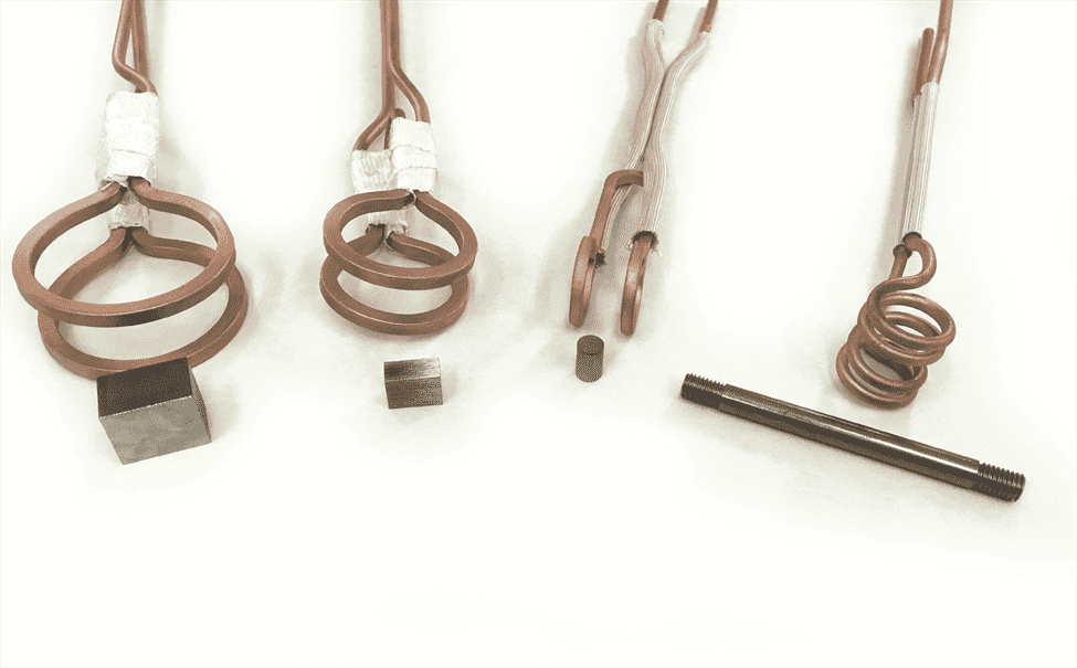
Fig. 12.11 Induction Coils.
| Part Number | Description | Sold As |
|---|---|---|
| HTR5007 | Round Coil | Ea. |
| HTR5006A | Uniaxial Compression Coil | Ea. |
| HTR5009A | Small Plane Strain Coil | Ea. |
| HTR5008A | Large Plane Strain Coil | Ea. |