11. Specialty Gleeble System Solutions
11.1. HDS-V40
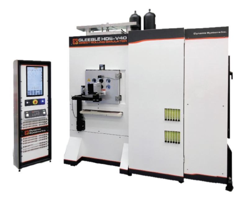
Fig. 11.1 Gleeble HDSV-40.
Unparalleled Technology for Process Development
Continuous casting followed by direct rolling (CC-DR) offers steelmakers the opportunity for substantial energy savings and reduced capital expenditures which, in turn, can lower costs and increase profits.
The HDS-V40 is the only commercially available laboratory system capable of simulating direct rolling, from the continuous caster to the end of the hot rolling process, all in one continuous sequence, using a single specimen. Steelmakers can explore the promise of continuous casting and direct rolling (CC-DR) on an affordable, reproducible, laboratory scale. In addition to direct rolling, this system can be used for simulating semi-solid rolling (liquid metal core reduction), plane strain compression, hot rolling and forging.
Thermal and Mechanical Systems
The HDS-V40 uses the Gleeble direct resistance heating method, but expands the technology to permit the use of larger specimens. The larger specimens allow materials properties testing after deformation.An innovative melting containment system features a crucible that holds the molten material in place and can be removed prior to deformation.
Unprecedented Flexibility
No other system offers so much flexibility to perform melting, solidification and deformation simulations in a controlled atmosphere. The HDS-V40 can perform plane strain compression tests on different material conditions including:
- Different parts of the melt zone
- Semi-solid material
- Previously melted material
- Re-solidified material
Additionally, the deformation anvils have separate heating controls. The temperature of the anvils can be adjusted independent of the specimen, simulating an actual rolling mill. An optional optical dilatometer allows collection of transformation data as the specimen cools.
Feedback Control
On the HDS-V40, the user can control the test process using either stroke or strain as the feedback variable to the control software. Strain control is based on the stroke feedback loop. Constant strain rates and non-linear strain rates can be programmed using stroke as the feedback variable within the limits of high-speed testing described in the previous section.
HDS-V40 Capabilities at a Glance
|
|
| Part Number | Description | Sold As |
|---|---|---|
| HDS-V40-1.7-150 | Gleeble HDS-V40 Direct Rolling Simulator | System |
11.1.1. Hydro-Mechanical
The HDS-V40 offers a high-speed mechanical system with unmatched performance. The latest in state-of-the-art hydraulic valves combined with an innovative hydraulic system create a high-speed servo system. The unique, patented Hydrawedge system allows independent control and programming of Strain and Strain Rate. The overall system has eight (8) control axes. Five are servo-hydraulic, three are thermal.
Another feature of this physical simulator is a mechanical system that permits moving the entire specimen and jaw system off the anvil centerline. Normally, the specimen is deformed at the center of the mid-span, where the liquid thickness during solidification is the same on both sides of the anvil. However, as a means of more accurately simulating semi-solid rolling, the specimen can be moved from side to side, enabling sequential compressions to deform the thickest part of the specimen.
| Characteristic | Specification |
|---|---|
| Test Frame | Vertical type with dual 120 mm (4.9 inches) diameter columns |
| Mechanical System | Closed-loop hydraulic servo control |
| Data Acquisition Channels | User selectable, up to 16 channels simultaneously, 18-bit ADC |
| Data Sampling Rate | User selectable, up to 50 kHz. |
| Maximum Static Force in Compression | 40,000 kgf (~ 88,184 lbf) (392 kN) |
| Maximum Stroke Rate - Both Rams Compressing Simultaneously | 1,700 mm/s (66.92 in/s) in compression |
| Maximum Stroke Rate - Each Ram Compressing Individually | 850 mm/s (33.47 in/s) in compression |
| Minimum Stroke Rate | 0.005 mm/s (1.96x10⁻⁴ in/s) compression |
| Maximum Combined Stroke Distance | 40 mm (1.57 in) |
| Maximum Number of Compression Hits | No Specific Limit |
Note
The total number of compression hits possible is dependent upon many test characteristics. These include the number of deformations, the initial position of the hydraulic stroke, and time between deformations.
Note
Accuracy is measured at a temperature of 23°C (73°F). Maximum stroke rates are at a hydraulic pressure of 203 bar (2,950 psi) ±3 % and an oil temperature of 30°C (86°F).
Load Cell
| Characteristic | Specification |
|---|---|
| Hysteresis | ±0.08 % of full scale |
| Overload Rating | 150 % of capacity |
| Deflection - Full Scale | 0.076 mm (0.003 in) |
| Force Measurement Accuracy | ±0.5 % of full scale |
| Force Measurement Resolution | ±1.5 kgf (3.2 lbf) (0.014 kN) |
| Force Measurement Response Time | 0.1 msec |
Note
Accuracy is measured at a temperature of 23°C (73°F). Maximum stroke rates are at a hydraulic pressure of 203 bar (2,950 psi) ±3 % and an oil temperature of 30°C (86°F).
Stroke Transducer
The opposing anvils of the HDS-V40 system is equipped with a measurement transducer. The stroke transducer serves to control the rate of specimen deformation.
| Characteristic | Specification |
|---|---|
| Type | LVDT |
| Linear Range | ±50.8 mm (±2. in) |
| Stroke Measurement Accuracy | ±0.25 % of full scale |
| Stroke Measurement Resolution | 0.0027 mm (1.063x10⁻⁴ in) |
| Stroke Measurement Response Time | 0.5 msec |
Note
Accuracy is measured at a temperature of 23°C (73°F). Maximum stroke rates are at a hydraulic pressure of 203 bar (2,950 psi) ±3 % and an oil temperature of 30°C (86°F).
Wedge Transducer
The opposing anvils of the HDS-V40 system is equipped with a measurement transducer. The wedge transducer serves to control the amount of specimen deformation.
| Characteristic | Specification |
|---|---|
| Type | LVDT |
| Linear Range | ±50.8 mm (±2. in) |
| Wedge Measurement Accuracy | ±0.25 % of full scale |
| Wedge Measurement Resolution | 0.0027 mm (1.063x10⁻⁴ in) |
| Wedge Measurement Response Time | 0.5 msec |
Note
Accuracy is measured at a temperature of 23°C (73°F). Maximum stroke rates are at a hydraulic pressure of 203 bar (2,950 psi) ±3 % and an oil temperature of 30°C (86°F).
Maximum Dynamic Force
Maximum Dynamic Force is based on the following graph. For a given stroke speed the hydraulic system will provide a corresponding force. All performance figures for the system are based on operating in the region below the force vs. stroke curve. The specifications are not valid for tests conducted outside this operating range.
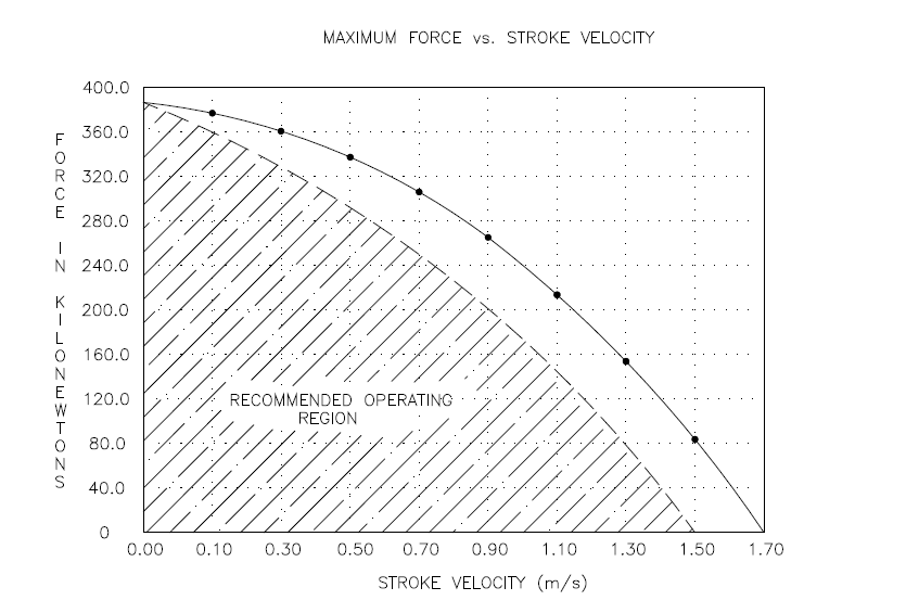
Fig. 11.2 Force vs. Stroke Velocity for HDS-V40.
The above chart shows the optimal performance of the system when both hydraulic rams are operating at full compression speed. The rated performance specification is for the maximum stroke rate with no load, using both rams.
Limits of High-Speed Testing
While the high-speed servo-systems provide the capability for high-speed compression and tension testing, there are certain limitations in the overall system which must be observed.
For all types of operation the Stroke Rate and Force must be within the operating range as described in the Maximum Force vs. Stroke graph.
For constant Strain Rate programs the duration of the deformation for each hit must be ten times the rated response time of the hydraulic servo valve. The Gleeble system uses high-speed valves with a rated response time of 0.006 seconds. Therefore the duration of the actual deformation of the material during the hit must be equal to or greater than 0.060 seconds.
11.1.2. Thermal Subsystems
The mechanical configuration of the HDS-V40 is based on handling a large melt zone. Since the specimen has no strength while in the liquid state, a composite crucible is used to support the melted material. The crucible has an open top an open top, but supports both the sides and the bottom of the specimen. The unique composite crucible permits a cooling medium to be sprayed around the specimen’s top, sides, and bottom. The volume of cooling media can be adjusted to provide controlled cooling and any shell formation desired on the cast material. The ends of the specimen are retained in water-cooled grips, preventing the melting from occurring beyond the end of the crucible. The crucible is mounted under the specimen with two retractable arms that provide support for the crucible during the casting process. To ensure efficient melting and to control segregation, the system is designed to provide electromagnetic stirring of the melt pool. Melt superheat may be limited due to the open top of the crucible.
The fragile liquid specimen, with its thin, solidified shell, requires that any deformation be balanced. The specimen should not move in the direction of deformation force while being deformed. To ensure any specimen moment does not occur, two opposing vertical, servo-hydraulic, rams are used. One ram in mounted in the top crosshead of the machine and the other ram is mounted in the bottom crosshead. The rams are synchronized to start and finish deforming the specimen at the same time and velocity.
When the specimen mid-span melts, the level of liquid at the top of the specimen is depressed. The liquid level is brought back to the original height by compressing the specimen. The amount of compression can be programmed into a test manually or automatically. This compression returns the specimen to its original thickness prior to solidification. During solidification the specimen is further compressed to accommodate any shrinkage which may occur as the specimen solidifies.
| Characteristic | Specification |
|---|---|
| Heating System Type and Control | Direct resistance with closed-loop control |
| Temperature Controller | Digital closed-loop control using 18-bit ADC and 32-bit digital processor |
| Temperature Range | Room Temperature to 1,550°C (2,822°F) |
| Temperature Monitoring Source | Thermocouple |
| Thermocouple Sampling Rate | Twice the Power Supply Frequency (100 - 120 Hz) |
| Resolution | ±1°C or°F |
| Maximum Number of Simultaneous Thermal Channels | 4 thermocouple channels |
| Accuracy of Control | ±1°C or°F (in steady state) |
| Accuracy of Measurement | ±1°C or°F or ±1 % of temperature (whichever is greater) plus the accuracy of the thermocouple wire (in steady state) |
11.1.2.1. Heating Rates
Heating rates are based on using a 480 V / 200 A power supply and 1018 carbon steel specimens.
| Specimen | Orientation | Drawing Number | Maximum Heating Rate |
|---|---|---|---|
| °C/s (°F/s) | |||
| 10 mm dia x 50 mm wide x 165 mm long | Lengthwise | SMF005B | 5 (9) |
| 10 mm dia x 15 mm long | SMC203B | 1 (1.8) | |
Note
As the specimen size, diameter, length, or cross-sectional area increases the effective heating rate will decrease.
11.1.2.2. Cooling Rates
The Gleeble system is able to control the specimen cooling rate based on conductive heat transfer. The efficiency and maximum rate of conductive cooling is directly impacted by grip and specimen geometry, material, cleanliness, and system’s chilled process fluid flow rate.
Quenching after specimen melting, prior to complete solidification, can result in undesirable specimen surface conditions. Care should be taken to ensure that the specimen has solidified enough to withstand surface contact with the desired quenching media.
Surface Cooling Rate During Water Quenching
Cooling rates are achieved with a 1018 carbon steel specimen.
| Specimen | Free Span | Drawing Number | Temperature Range | Cooling Rate |
|---|---|---|---|---|
| °C (°F) | °C/s (°F/s) | |||
| 10 mm thick x 50 mm wide x 165 mm long - undeformed | SMF005 | Max Solid Temp - 800 (Max Solid Temp - 1,472) | 50 (90) | |
Surface Cooling Rate During Gas Quenching
Cooling rates are achieved with a 1018 carbon steel specimen.
| Specimen | Free Span | Drawing Number | Temperature Range | Cooling Rate |
|---|---|---|---|---|
| °C (°F) | °C/s (°F/s) | |||
| 10 mm thick x 50 mm wide x 165 mm long - undeformed | SMF005 | 800 - 500 (1,472 - 932) | 5 (9) | |
Surface Cooling Rate During Gas Quenching for Uniaxial Compression
Cooling rates are achieved with a 1018 carbon steel specimen and Uniaxial Compression Anvil set and quench spray heads.
| Specimen | Free Span | Drawing Number | Temperature Range | Cooling Rate |
|---|---|---|---|---|
| °C (°F) | °C/s (°F/s) | |||
| 27 mm long x 15 mm dia | SMC209 | 800 - 500 (1,472 - 932) | 5 (9) | |
11.1.3. Thermocouple Measurement Assemblies
The Dual Channel Thermocouple Input series of modules is designed to add thermocouple input channels to Gleeble 500 Series systems and the HDS-V40. Each module may be connected to any available Gleeble PnP port, providing two thermocouple input channels of a given type.
| Part Number | Thermocouple Type | Description |
|---|---|---|
| 59004 | K | Dual Channel Input Box |
| 59005 | S | Dual Channel Input Box |
| 59006 | R | Dual Channel Input Box |
| 59007 | B | Dual Channel Input Box |
| 59008 | E | Dual Channel Input Box |
| 59014 | J | Dual Channel Input Box |
Note
A single K-type Dual Channel Input Box is included standard if required.
11.1.3.1. Thermocouple Wire Types
Gleeble systems are capable of recording specimen temperature with various thermocouple wire types. The following types of thermocouple wire can be used on any Gleeble system.
| Part Number | TC Type | Material | Sold As |
|---|---|---|---|
| Operating Range: 0 - 1,450°C (32 - 2,642°F) | |||
| TC005 | R- or S- | Pt 100% | Inch |
| TC006 | R+ | Pt 87% - Rh 13% | Inch |
| TC009 | S+ | Pt 90% - Rh 10% | Inch |
| Operating Range: -200 - 1,250°C (-328 - 2,282°F) | |||
| TC014 | K- | Alumel | Spool |
| TC015 | K+ | Chromel | Spool |
| Operating Range: 0 - 1,700°C (32 - 3,092°F) | |||
| TC017 | B- | Pt 94% - Rh 6% | Inch |
| TC018 | B+ | Pt 70% - Rh 30% | Inch |
| Operating Range: 0 - 750°C (32 - 1,382°F) | |||
| TC030 | J+ | Fe 100% | Spool |
| TC031 | J- | Constantan | Spool |
| Operating Range: -200 - 900°C (-328 - 1,652°F) | |||
| TC032A | E+ | Chromega | Spool |
| TC033 | E- | Constantan | Spool |
| Operating Range: 0 - 2,320°C (32 - 4,208°F) | |||
| TC010 | C+ | W 95% - Re 5% | Inch |
| C- | W 74% - Re 26% | ||
Note
TC wire types C, K, J, and E have a nominal wire diameter of 0.254 mm (0.01 in). TC wire types R, S, and B have a nominal wire diameter of 0.2032 mm (0.008 in).
Note
Gleeble systems can support additional thermocouple wire types not shown. Contact Dynamic Systems for additional information regarding the use of alternate thermocouple wire types.
Note
Each thermocouple wire type requires a corresponding Dual Channel Thermocouple Input Module for temperature measurement in Gleeble 500 Series systems or the HDS-V40.
11.1.4. Measurement Gauges and Kits - HDS-V40
11.1.4.1. HDS-V40 Lengthwise Extensometer - Range: ±50.8 mm
The HDS-V40 is supplied with a Lengthwise Strain Gauge Assembly. The L-Strain gauges mounted on the anvil attachment points to provide precise measurement of the anvil movements.
| Characteristic | Specification |
|---|---|
| Type | LVDT |
| Linear Range | ±50.8 mm (2.0 in) |
| Accuracy | ±0.25 % of full scale |
| Resolution | 0.0027 mm (1.063x10⁻⁴ in) |
| Response Time | 0.5 msec |
| Gauge Length | 0 - 31 mm (0 - 1.22 in) |
| Maximum Usable Stroke Rate | 1, 700 mm/s (66.92 in/s) |
| Part Number | Description | Sold As |
|---|---|---|
| 3V924 | L-Strain Gauge Assembly - HDS-V40 | Kit |
11.1.4.2. HDS-V40 Uniaxial Compression Anvil Assembly
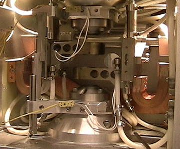
Fig. 11.3 HDS-V40 Uniaxial Compression Anvil Assembly as installed.
The model 3V968 Uniaxial Compression Anvil Assembly is used for uniaxial compression tests. An alternative load cell is included to allow more precise measurements of the forces encountered in uniaxial compression tests. The anvil face size is 25 mm (0.984 in ) diameter and uses the ISO-T design developed by DSI to provide uniform temperatures and minimum barreling of the specimen during compression tests.
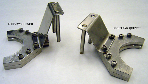
Fig. 11.4 Uniaxial specimen quench spray heads are included with this option.
| Part Number | Description | Sold As |
|---|---|---|
| 3V968 | Uniaxial Compression Anvil Assembly - HDS-V40 | Kit |
11.1.4.3. HDS-V40 Plane Strain Anvil Assembly
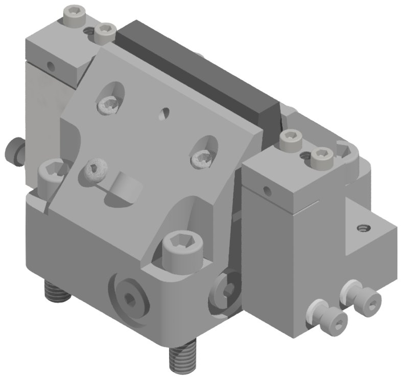
Fig. 11.5 HDS-V40 Plane Strain Heated Mk II Anvil Assembly.
| Part Number | Description | Sold As |
|---|---|---|
| 3V890 | Plane Strain Heated Mk II Anvil Assembly - 10 x 70 mm (0.393 x 2.755 in) - HDS-V40 | Kit |
11.1.4.4. HDS-V40 Melting Crucible Retractors and Control Unit
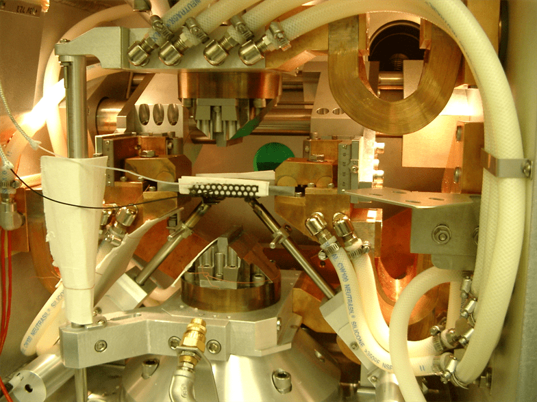
Fig. 11.6 HDS-V40 HDS-V40 Melting Crucible as installed.
| Part Number | Description | Sold As |
|---|---|---|
| 3V905 | Melting Crucible Retractors and Control Unit - HDS-V40 | Kit |
11.1.4.5. Non-Contact LED Optical Micrometer - Ranges: ±60 mm ±6 mm ±0.6 mm
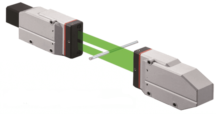
Fig. 11.7 Non-Contact Optical Dilatometer & Extensometer - DSI# 59032.
The 59032 Non-Contact LED Optical Micrometer uses a high-intensity GaN long-life LED combined with an HL-CCD sensor to provide high-speed measurements with no moving parts. Easy-to-use menu-driven setup software is included with the unit to allow configuration of predefined measurement ranges via the Gleeble HMI. Settings can be stored, recalled, and easily changed for a variety of test conditions. The 59032 Non-Contact LED Optical Micrometer can be used to measure in either a crosswise configuration or a lengthwise configuration.
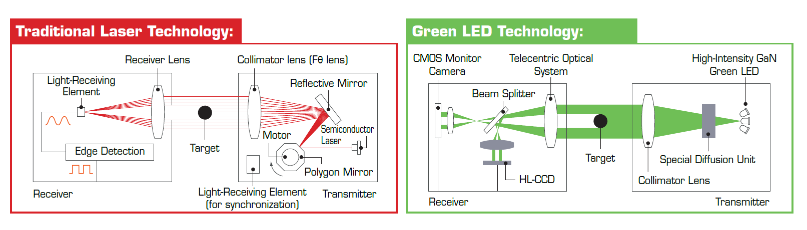
Fig. 11.8 Optical Measurement Comparison.
Green LED Technology
The green LED light is distributed as a uniform parallel light beam, and is applied to a target. The edge between the bright and dark areas on the HL-CCD sensor is detected and translated into a measured value, such as a specimen’s outer diameter.
Traditional Laser Technology
In a conventional laser optical measuring device, the laser beam is projected onto a rotating polygonal mirror. The reflected light scans the measurement range, then reaches the receiving element. To improve speed and accuracy of this laser measuring device, the mirror’s rotating motor would need to operate at a faster rate, sacrificing durability and reliability.
| Characteristic | Specification | ||
|---|---|---|---|
| Range | ±60 mm (±2.36 in) | ±6 mm (±0.236 in) | ±0.6 mm (±0.0236 in) |
| Resolution | 12 μm (4.72 x 10⁻⁴ in) | 1.2 μm (4.72 x 10⁻⁵ in) | 0.3 μm (1.18 x 10⁻⁵ in) |
| Accuracy | ±68 μm (±2.67 x 10⁻³ in) | ±14 μm (±5.51 x 10⁻⁴ in) | ±8.6 μm (±3.33 x 10⁻⁴ in) |
| Sampling Rate | 16 kHz | ||
| LED Type | InGaN Green | ||
| Ambient Luminescence | 3,000 Lux or lower | ||
| Smallest Detectable Object | 0.8 mm (0.031 in) | ||
| Serial Communication | RS-232, parity:none, baud:9600 | ||
| Analog | Output ±10 VDC | ||
| Output Impedance | ~100 ohms | ||
| Supply Power | 24 VDC | ||
| Maximum Power Consumption | 1.2 amps | ||
| Operating Temperature | 0 - 50°C (32 - 122°F) | ||
| Operating Humidity | 20 - 85 % RH | ||
| Mounting | Crosswise or Lengthwise | ||
Note
Measuring range may be limited by vacuum chamber window size.
Danger
Never look directly into the scanning optical system LED transmitting head. Never point the transmitting head away from the vacuum tank while the power is on.
| Part Number | Description | Sold As |
|---|---|---|
| 59032 | Non-Contact Optical LED Dilatometer and Extensometer | Ea |
11.1.5. Additional Features
Vacuum System
Gleeble vacuum pumping systems are designed to perform as an integral part of the HDS-V40 system. The vacuum pumping system consists of the complete pumping system and its electronic controls. The entire unit is powered and controlled from the HDS-V40 control console. It provides vacuum pressures of 5 x 10⁻⁴ Torr. The system is equipped with a 350 L/min (92.5 gal/min) roughing pump and a 1,250 L/min (330 gal/min) diffusion pump.
Operation of the Vacuum Pumping Systems is fully automatic. The system status is monitored by the control software and pressure readings are available on the VPM monitor. The system can be used as a roughing pump alone for experiments that do not require extreme vacuum. The tank may be rough pumped and then backfilled with an inert gas such as argon or nitrogen.
| Characteristic | Specification |
|---|---|
| Voltage Rating | 380/400 VAC |
| 460/480 VAC | |
| Roughing Pump | 350 L/min (92.5 gal/min) |
| Diffusion Pump | 1,250 L/min (330 gal/min) |
| Diffusion Pump Size | 102 mm (4 in) diameter |
| Diffusion Pump Cooling | Gleeble chilled process fluid |
| Lowest Achievable Diffusion Pump Vacuum Pressure | 5 x 10⁻⁴ Torr |
Note
The achievable vacuum pressure of the HDS-V40 vacuum tank, 5 x 10⁻⁴ Torr is only possible in a dry atmosphere (relative humidity less than 60 %) with a clean, dry, and properly sealed vacuum tank.
Warning
The Gleeble vacuum tank is designed to operate under vacuum or atmospheric pressure, with either air or an inert gas surrounding the specimen. Positive atmospheric pressure, explosive, flammable or corrosive gases, or any mixtures of these gases, should never be used as part of the vacuum tank atmosphere.
Hydraulic Power Unit
Gleeble HDS-V40 systems are equipped with an independent hydraulic power unit (HPU). The HPU is the primary source of mechanical motion for these Gleeble systems. The HPU is capable of regulating the output pressure of the hydraulic fluid based on Gleeble system configuration.
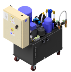
Fig. 11.9 Gleeble Hydraulic Power Unit.
Typical configurations allow the user to choose between a high and a low output pressure. These pressures can be manually selected with a button on the HMI or through the programming of a Gleeble test. Special configurations of the Gleeble will limit the pressures available for testing.
The Gleeble HPU uses one branch of the process fluid chiller for automatic computer control of the hydraulic oil temperature. By automatically regulating the temperature of the hydraulic oil, the Gleeble is capable of maintaining peak performance in a variety of ambient temperature environments. The HPU is protected by a high oil temperature sensor, a high oil level sensor, and a low oil level sensor.
| Characteristic | Specification | |
|---|---|---|
| Pump Motor | 40 hp | |
| Variable Pressure Output | Low Pressure | 68.94 bar (1000 psi) |
| High Pressure | 206.84 bar (3000 psi) | |
| Hydraulic Oil Reservoir | 568 L (150 gal) | |
11.1.6. HDS-V40 Physical Dimensions
| Equipment | Height | Depth | Width | Weight |
|---|---|---|---|---|
| Control Console | 180 cm (71 in) | 66 cm (26 in) | 61 cm (24 in) | 195 kg (430 lb) |
| Hydraulic Power Unit | 63.5 cm (25 in) | 121.92 cm (48 in) | 91.44 cm (36 in) |