10. Gleeble 525
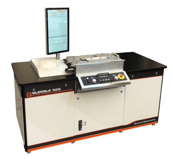
Fig. 10.1 Gleeble 525.
A Dedicated Simulation System for Optimizing Continuous Annealing, Galvanizing and Coating Lines
The Gleeble 525 Strip Annealing Simulator is a low-cost system built specifically for simulating thermal cycles in sheet specimens, including continuous annealing lines, batch annealing, quenching and tempering (Q+T), quenching and partitioning (Q+P) and other heat treatment processes. The Gleeble 525 is designed to be used on the production floor or in a research lab. This easy-to-use system can quickly run tests and simulations on wide dimension specimens, to help researchers make better processing decisions.
Overview
Gleeble technology makes it easy to reproduce real-world annealing thermal cycles on steel sheet or strip materials. Unlike expensive mill trials, simulations help staff quickly and efficiently optimize annealing procedures to improve profitability, increase production, and reduce waste by rapidly providing the information needed to make better processing decisions.
Build More Efficient Line Schedules
Simulation data help production line metallurgists reduce the number of expensive mill trials they run and provides insight to more efficiently schedule different grades, gauges and specified characteristics. The Gleeble 525 can rapidly and dynamically heat and quench sheet specimens to accurately simulate annealing, galvanizing, and coating line processing. The system can be used to reproduce and evaluate existing processes, experiment with process modifications, or troubleshoot problems.
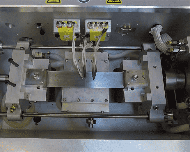
Fig. 10.2 Specimen installed in a Gleeble 525.
Simulation of these processes offers the following benefits:
Better understanding of the time/temperature relationships and processing window limits for producing desired material characteristics.
Improved product quality - simulations help determine the conditions needed to optimize material properties and meet the high demanding requirements for advanced high strength steel (AHSS)
Better process window definition and improved efficiency through reduced use of:
- Warmer coils
- Reduce secondary coils
- Test coils
Accelerated new product development
Development of annealing cycles to meet specification and to salvage off-chemistry or misprocessed coils
Adjustment of processing settings for different alloys and material grades
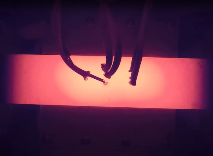
Fig. 10.3 Gleeble 525 specimen’s thermal gradient.
DSI Strip Annealing Systems Offer the Following Capabilities:
Ultra-Fast Heating
All Gleeble strip annealing systems utilize the same ultra-fast direct resistance heating that has made Gleeble systems a staple at the world’s leading metals producers.
Proportional Quench
A dynamic cooling system with custom gas-quench spray heads that allows fast yet controlled cooling.
Complex Thermal Cycles
Users can easily program complex temperature profiles, including heating, holding, controlled cooling, reheating and quenching. This allows for accurate simulation of production line processes.
Large Uniform Temperature Zones
Great care has been taken to maximize temperature uniformity in the test specimens, allowing for simulations that are more representative of production processes. This resulting in a more representative post-treatment material condition.
Environmental Control
Specimens can be tested in vacuum, air or inert gas.
Tension Application
Tension can be applied to the specimen to prevent buckling and to simulate roll tension forces.
| Part Number | Description | Sold As |
|---|---|---|
| 525 | Gleeble 525 Strip Annealing Simulator | System |
10.1. Advanced Gleeble Control
Gleeble 500 Series systems are equipped with advanced Gleeble control systems similar to the Gleeble Touch Control of the 3000 Series systems. The control system of a Gleeble 500 Series system includes an intuitive user display with a large and easy-to-use touchscreen. Advanced software and hardware provide state-of-the-art performance with accuracy and dependability at the heart of the design.
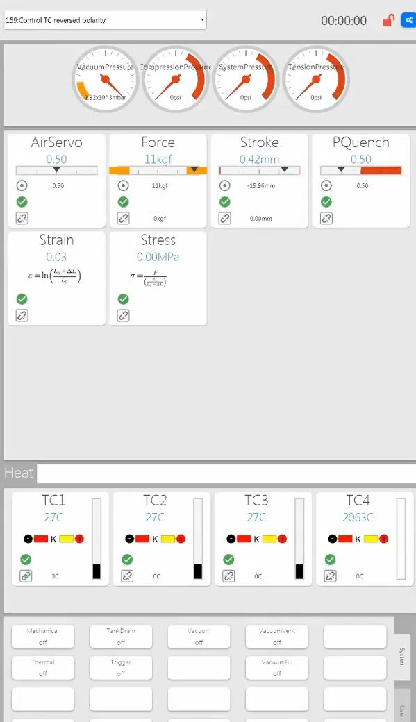
Fig. 10.4 Gleeble 525 User Interface Display.
10.2. Pneumatic - Mechanical
The Gleeble 525 includes a pneumatic system that is used to apply light tension to the specimen. Tension is applied to simulate annealing line tension and to help prevent specimen buckling. The pneumatic system is not intended to conduct deformation or tensile testing. Tension is measured and controlled using a load cell.
| Characteristic | Specification |
|---|---|
| Test Frame | Horizontal framework and structural vacuum tank |
| Mechanical System | Closed-loop pneumatic servo control |
| Recommended Force in Tension | 50 kgf (110 lbf) (0.49 kN) |
| Maximum Stroke Distance | 50.8 mm (2 in) |
| Minimum Compressed Air Supply | 350 L/min (95.46 gal) for 3 s at 5.5 bar (79.77 psi) |
| Servo Valve Response Time | 4.8 ms |
Load Cell
The Gleeble 525’s load cell is mounted directly to the stationary jaw. It is used to measure the force exerted on the specimen by the pneumatic system.
| Characteristic | Specification |
|---|---|
| Maximum Force in Tension | 225 kgf (496 lbf) |
| Non-linearity | ±0.1 % of full scale |
| Hysteresis | ±0.08 % of full scale |
| Non-Repeatability (Maximum) | ±0.02 % of full scale |
| Overload Rating | 150 % of full scale |
| Deflection - Full Scale | 0.051 mm (0.002 in) |
10.3. Thermal Subsystem
The Gleeble 525 offers high-speed heating and dynamic quenching systems to simulate real-world thermal cycles.
Direct resistance heating provides the ability to reproduce the wide variety of thermal profiles that materials undergo in actual processes. This is critical to the success of thermal-mechanical testing and physical simulation. All Gleeble systems have high-speed heating and cooling rates that can accurately replicate nearly any thermal profile required.
| Characteristic | Specification |
|---|---|
| Heating System Type and Control | Direct resistance with closed-loop control |
| Temperature Control | Digital closed-loop control using an 18-bit ADC and a 32-bit digital processor. |
| Temperature Range | Room temperature to 1,000°C (1,832°F) |
| Time at Maximum Temperature | 5 min (When testing with SMF110 specimens) |
| Temperature Monitoring Source | Thermocouple |
| Thermocouple Sampling Rate | Twice the Power Supply Frequency (100 - 120 Hz) |
| Resolution | ±1°C or°F |
| Maximum Number of Simultaneous Thermal Channels | 8 thermocouple channels |
| Accuracy of Control | ±1°C (in steady state) |
| Accuracy of Measurement | ±1 % of temperature plus the accuracy of the thermocouple wire (in steady state) |
Note
As the specimen size, diameter, length, or cross-sectional area increases the effective heating rate will decrease.
10.3.1. Thermocouple Measurement Assemblies
The Dual Channel Thermocouple Input series of modules is designed to add thermocouple input channels to Gleeble 500 Series systems and the HDS-V40. Each module may be connected to any available Gleeble PnP port, providing two thermocouple input channels of a given type.
| Part Number | Thermocouple Type | Description |
|---|---|---|
| 59004 | K | Dual Channel Input Box |
| 59005 | S | Dual Channel Input Box |
| 59006 | R | Dual Channel Input Box |
| 59007 | B | Dual Channel Input Box |
| 59008 | E | Dual Channel Input Box |
| 59014 | J | Dual Channel Input Box |
Note
A single K-type Dual Channel Input Box is included standard if required.
10.3.1.1. Thermocouple Wire Types
Gleeble systems are capable of recording specimen temperature with various thermocouple wire types. The following types of thermocouple wire can be used on any Gleeble system.
| Part Number | TC Type | Material | Sold As |
|---|---|---|---|
| Operating Range: 0 - 1,450°C (32 - 2,642°F) | |||
| TC005 | R- or S- | Pt 100% | Inch |
| TC006 | R+ | Pt 87% - Rh 13% | Inch |
| TC009 | S+ | Pt 90% - Rh 10% | Inch |
| Operating Range: -200 - 1,250°C (-328 - 2,282°F) | |||
| TC014 | K- | Alumel | Spool |
| TC015 | K+ | Chromel | Spool |
| Operating Range: 0 - 1,700°C (32 - 3,092°F) | |||
| TC017 | B- | Pt 94% - Rh 6% | Inch |
| TC018 | B+ | Pt 70% - Rh 30% | Inch |
| Operating Range: 0 - 750°C (32 - 1,382°F) | |||
| TC030 | J+ | Fe 100% | Spool |
| TC031 | J- | Constantan | Spool |
| Operating Range: -200 - 900°C (-328 - 1,652°F) | |||
| TC032A | E+ | Chromega | Spool |
| TC033 | E- | Constantan | Spool |
| Operating Range: 0 - 2,320°C (32 - 4,208°F) | |||
| TC010 | C+ | W 95% - Re 5% | Inch |
| C- | W 74% - Re 26% | ||
Note
TC wire types C, K, J, and E have a nominal wire diameter of 0.254 mm (0.01 in). TC wire types R, S, and B have a nominal wire diameter of 0.2032 mm (0.008 in).
Note
Gleeble systems can support additional thermocouple wire types not shown. Contact Dynamic Systems for additional information regarding the use of alternate thermocouple wire types.
Note
Each thermocouple wire type requires a corresponding Dual Channel Thermocouple Input Module for temperature measurement in Gleeble 500 Series systems or the HDS-V40.
10.3.2. Heating Rates
Heating rates are based on using a 480 V / 200 A power supply, standard Stainless Steel top and bottom grips (GN91101B/T), and 1018 carbon steel specimens.
| Specimen Type | Maximum Heating Rate | Drawing Number |
|---|---|---|
| °C/s (°F/s) | ||
| 1 mm x 50 mm x 260 mm | 50 (90) | SMF109B |
| 2 mm x 50 mm x 260 mm | 25 (45) | SMF110B |
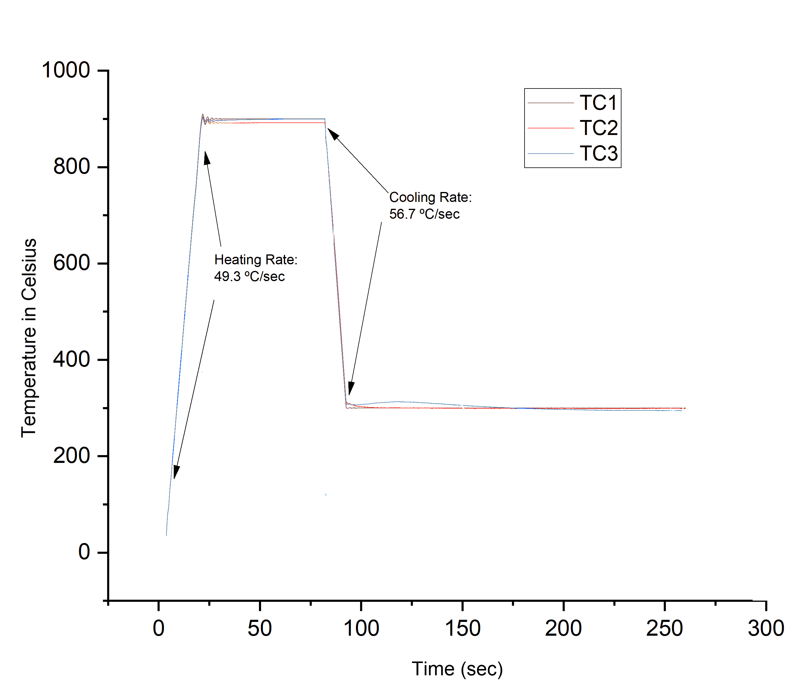
Fig. 10.5 Heating and cooling rates during a Gleeble 525 test.
10.3.3. Cooling Rates
Quench Cooling Rates
The Gleeble 525 includes a proportional quench system which dynamically cools the specimen using a custom-designed quench spray head. The quench system uses a gas supply such as nitrogen, argon, or compressed air.
The free cooling rates are achieved using standard Stainless Steel top and bottom grips (GN91101B/T), 1018 carbon steel specimens, and a Proportional Quench System valve.
| Specimen | Quench Rate | Drawing Number | Quench Medium |
|---|---|---|---|
| °C/s (°F/s) | |||
| 1 mm x 50 mm x 260 mm | 57 (102.6) | SMF109B | Nitrogen Gas |
| 2 mm x 50 mm x 260 mm | 28 (50.4) | SMF110B | Nitrogen Gas |
10.3.4. Temperature Uniformity Within the Specimen
The Gleeble system has the unique ability to control the temperature uniformity and thus the thermal gradient within the test specimen. Tests can be performed with very uniform temperature within the specimen work zone, equivalent to a furnace-based test, or with the large thermal gradients needed to accurately simulate welding and other processes.
When using Joule heating, the current density in a Gleeble specimen is uniformly distributed across the entire specimen cross-sectional area, meaning that the Gleeble is able to heat the entire specimen simultaneously, from surface to center. Since the Gleeble grips are cool, the heat generated in the specimen will diffuse into the grips, creating a thermal gradient with the ends of the specimen generally being cooler than the center. The severity of the steady state thermal gradient is defined by the rate of heat generated in the specimen, offset by the heat lost to the grips. This gradient can be controlled by utilizing grips of materials with differing thermal and electrical conductivity and contact area. Thermally and electrically conductive grips with a large specimen contact area will be kept cold more readily with the water-cooled jaws, and will accept significant heat from the specimen, resulting in “cold ends” and a very steep thermal gradient.
Grips with smaller contact area and higher thermal resistance will pull much less heat from the specimen. Grips manufactured from material with higher electrical resistance will, themselves, heat under the same current that is heating the specimen. These factors will result in very little heat being pulled from the specimen and a very flat thermal gradient. In some cases the grips or anvils holding the specimen may reach temperatures equal to or higher than the specimen, creating a “reverse” thermal gradient.
When considering Gleeble thermal gradients, it is also critical to differentiate between the axial thermal gradient (along the length of the specimen), and the transverse thermal gradient (across the diameter or cross section of the specimen). Even in situations where a specimen experiences a very high axial thermal gradient, the transverse, or crosswise thermal gradient will be very small. This ability to generate isothermal planes is a critical benefit of the Gleeble. In contrast to furnace or induction heating methods, where the specimen can only be heated on the surface or to a limited “skin depth”, the center of a Gleeble specimen is heated at the same rate as the surface regardless of the heating rate. This ability to generate isothermal planes allows for the Gleeble platform to perform dilatometry and welding heat affected zone experiments at heating and cooling rates relevant to welding and other processes on specimens that are large enough for subsequent mechanical property or toughness testing. This is not feasible on furnace or inductively-heated systems that rely on thermal conduction to heat the center of the specimen. Axial thermal uniformity within a specimen is reported as the difference between the specimen’s center to edge thermal measurements and is dependent upon:
|
|
Thermal Uniformity
Thermal uniformity within the specimen, the difference between the center-point temperature measurement and the edge temperature measurement, is verified by measuring specimen temperature with thermocouples secured onto the specimen.
Thermocouple Placement
All thermocouple location measurements are indexed from the left and top of the specimen. Secure thermocouples at the following locations:
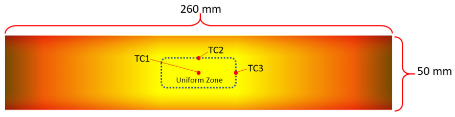
Fig. 10.6 Thermocouple Placement.
Note
All measurements are taken from the left and top of the specimen.
| Characteristic | Specification |
|---|---|
| Uniform Temperature Zone | 20 mm x 50 mm area |
| Steady-State Thermal Gradient | 20°C (68°F) |
| Thermal Gradient On Heating | 20°C (68°F) |
| Thermal Gradient On Cooling/Quenching | 30°C (86°F) |
Reproducibility
Thermal gradients in resistance-heated specimens are dependent upon on the properties of the specimen. All specimens with the same physical, mechanical, electrical, and chemical properties will have the same gradients within the accuracy of the thermal system, provided that the specimen grips are in good condition.
10.4. Specimen Size Considerations
The Gleeble 525 uses the same specimen geometries as the General-Purpose MCU - Strip Annealing Kit. This specimen’s geometry enables the an ASTM-E8 dog bone-shaped specimen to be cut out of the thermally-uniform center. Contact Dynamic Systems for assistance identifying a recommended specimen geometry.
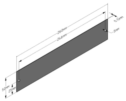
Fig. 10.7 Strip Annealing Specimen - SMF109.
| Popular Specimen Sizes | |||
|---|---|---|---|
| Length | Width | Thickness | Drawing Number |
| 250 mm | 50 mm | 0.5 mm | SMF119 |
| 250 mm | 50 mm | 1 mm | SMF109 |
| 250 mm | 50 mm | 2 mm | SMF110 |
10.5. Additional Features
Vacuum Tank
One of the distinguishing features of a Gleeble system is the ability to test materials in a controlled atmosphere. Researchers can simulate processes and test specimens in standard atmosphere, in rough vacuum, in high vacuum or in an inert gas environment. This environmental control is possible due to the large vacuum tank, also referred to as a “test chamber,” that is incorporated into every Gleeble. The vacuum tank is fully integrated into the Gleeble system and can be controlled with manual controls or through software controls. A popular approach to atmosphere control in the Gleeble includes “washing cycles” which involve pumping down to a rough vacuum in the tank and then backfilling with an inert gas. This can be conducted multiple times to ensure that the desired atmosphere is achieved.
Gleeble vacuum tanks include a large viewing port incorporated into the tank door to allow visual observation of simulations. In some cases, viewing windows are removed or covered to protect users from the light intensity of specimens at elevated temperatures.
Feedthroughs are an important feature in the Gleeble vacuum tanks. They allow researchers to install equipment that can measure or interact with the specimen during a test while still controlling the atmosphere. For example, vacuum-sealed electrical feedthroughs allow communication with transducers such as thermocouples, load cells, and strain transducers. Piping feedthroughs enable atmosphere control (e.g. inert gas backfill and vacuum supply) as well as allowing quenching media to be utilized.
Warning
The Gleeble vacuum tank is designed to operate under vacuum or atmospheric pressure, with either air or an inert gas surrounding the specimen. Positive atmospheric pressure, explosive, flammable or corrosive gases, or any mixtures of these gases, should never be used as part of the vacuum tank atmosphere.
10.6. Gleeble Physical Dimensions
The Gleeble 500 Series systems were designed to fit through a standard entryway. With a depth measuring just 87 cm (34 in), with the Lower Console Assembly removed. The system will occupy a space of 3 x 4 m (9.84 x 13.12 ft) for general operation. This does not include the additional space required for options such as a freestanding vacuum system option.
| Equipment | Height | Depth | Width | Weight |
|---|---|---|---|---|
| 500 Series System | 125 cm (49 in) | 97 cm (38 in) | 202 cm (80 in) | 800 kg (1,800 lb) |
10.6.1. Frame and Machine Stiffness
Gleeble 500 Series systems have a frame stiffness of 3.85 x 10⁻⁸ m/N (6.74 x 10⁻⁶ lbf).