24. Quench Systems
24.1. Quench Tanks
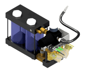
Fig. 24.1 High Flow Quench - DSI# 59013.
The Gleeble Quench Tank Systems are designed to increase the cooling capability of the Gleeble platform. DSI offers two standard Quench Tank System options, the 59013 High Flow and the 59038 Extended High Flow quench systems. Each option includes two independent quench medium tanks. These tanks can be used independently or simultaneously.
The quench system uses a gas or liquid cooling medium to remove thermal energy from the test specimen. The quench directly interfaces with the high-speed EtherCAT bus on all GTC and 500 Series systems. Spray heads are not included and must be purchased separately.
| Characteristic | Specification | |
|---|---|---|
| High Flow | Extended High Flow | |
| Volume of Quench Tanks | 1 liter (0.26 gal) per tank | 3 liters (0.792 gal) per tank |
| Number of Quench Tanks per System | 2 tanks | |
| Quench Medium Flow Control | One multi-turn needle valve per tank | |
| Maximum Air or Gas Output Pressure | 0 - 6.89 bar (0 - 100 psi) | |
| Part Number | Description | Sold As |
|---|---|---|
| 59013 | High-Flow Quench | Ea. |
| 59038 | Extended High-Flow Quench | Ea. |
Warning
Gleeble Quench Tanks are not designed to be used with flammable gases or liquids, including hydrogen gas. The maximum water temperature the Quench Tank can withstand is 38°C (86°F).
24.2. Quench Kits
24.2.1. 3000 Series Quench Spray Nozzle Kits
24.2.1.1. Open Quench Spray Nozzle Kit
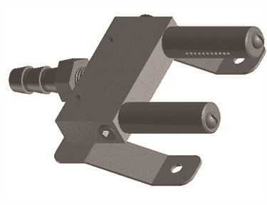
Fig. 24.3 Quench Spray Nozzle - DSI# GN9300AS1.
The GN9300AS1 Open Quench Spray Nozzle Kit features spray head designed to quench through specimen surface contact. The spray heads are mounted between the Gleeble’s Pocket Jaws, above and below the test specimen. Each kit includes specific spray nozzles for flat and round specimens. When the quench valves are turned on, the quenching medium flows through the spray heads toward the specimen. If the Gleeble is equipped with a vacuum system, the vacuum is turned off to prevent the quench medium from contaminating the vacuum pump. This quench spray nozzle kit can be used on the Pocket Jaws of the General-Purpose Mobile Conversion Unit MCU and the Low-Force Pocket Jaws for the Gleeble 3500 and 3800.
Note
The GN9300AS1 Open Quench Spray Nozzle Kit is not compatible with the Gleeble Induction Heating System (IHS) or Compression Test Adapter.
| Part Number | Description | Sold As |
|---|---|---|
| GN9300AS1 | Open Quench Spray Nozzle Kit - 3500 and 3800 | Kit |
| GN9300AS3 | Open Quench Spray Nozzle Kit - 3180 | Kit |
| Optional Accessories | ||
| GN9300B | Flat Spray Pattern - 1 Row - Quench Spray Nozzle (Included in GN9300AS3) | Ea. |
| GN9300C | Round Spray Pattern - 1 Row - Quench Spray Nozzle (Included in GN9300AS3) | Ea. |
| GN9300M | Flat Spray Pattern - 3-Row - Quench Spray Nozzle | Ea. |
| GN9300L | Round Spray Pattern - 3 Row - Quench Spray Nozzle | Ea. |
24.2.1.2. Multi-Function Open Quench Spray Nozzle Kit
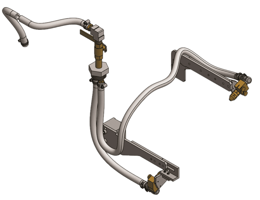
Fig. 24.4 Multi-Function Open Quench Spray Nozzle Kit - DSI# 31733.
The 31733 Multi-Function Open Quench Spray Nozzle Kit features a surface quenching design with sprayer nozzles that quench the specimen by direct contact with the quenching medium. The spray heads are mounted outside the Gleeble’s Pocket Jaws, above and below the test specimen. When the Multi-Function Quench Spray Nozzles are used, the quenching medium is sprayed directly on the specimen. If the Gleeble is equipped with a vacuum system, the vacuum is turned off to prevent the quench medium from contaminating the vacuum pump.
This quench spray nozzle kit can be used on the Pocket Jaws of the General-Purpose Mobile Conversion Unit MCU, the Low-Force Pocket Jaws for the Gleeble 3500 and 3800, the Compression Test Adapter, and with the Gleeble Induction Heating System (IHS).
| Part Number | Description | Sold As |
|---|---|---|
| 31733 | Multi-Function Open Quench Spray Nozzle Kit | Kit |
24.2.1.3. Hydrawedge II - Multi-Function Open Quench Spray Nozzle Kit
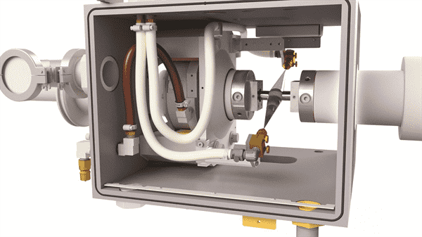
Fig. 24.5 Multi-Function Open Quench Spray Nozzle Kit - Hydrawedge II - DSI# 31735.
The 31735 Hydrawedge II - Multi-Function Open Quench Spray Nozzle Kit features a surface quenching design with sprayer nozzles that quench the specimen by direct contact with the quenching medium. The spray heads are mounted outside the Gleeble’s anvil faces, above and below the test specimen. When the Multi-Function Open Quench Spray Nozzles are used, the quenching medium is sprayed directly on the specimen. If the Gleeble is equipped with a vacuum system, the vacuum is turned off to prevent the quench medium from contaminating the vacuum pump.
The 37135 quench system is only used on the Hydrawedge II MCU and can be used with the Gleeble Induction Heating System (IHS).
| Part Number | Description | Sold As |
|---|---|---|
| 31735 | Hydrawedge II - Multi-Function Open Quench Spray Nozzle Kit | Kit |
24.2.1.4. Closed ISO-Q Quench Kits
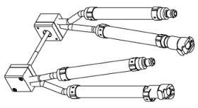
Fig. 24.6 ISO-Q Quench Heads - DSI# 38520.
The ISO-Q Closed Quench Spray Nozzle Kit provides a quenching method that does not compromise the vacuum in the chamber when quenching. The ISO-Q Quench System works with both the high-flow and extended high-flow quench systems on the 3500, 3800, and the 3180. The specimens for use with the ISO-Q quench system have holes in each end to accommodate the ISO-Q Quench Nozzles. This allows the quench medium to contact the specimen internally. When using this method of quenching, a vacuum or inert gas atmosphere can be maintained. This quench kit is typically used for Continuous Cooling Transformation (CCT) and Heat Affected Zone (HAZ) studies. The ISO-Q Quench System is sometimes referred to as a “closed quench” system.
| Part Number | Description | Sold As |
|---|---|---|
| 3500 and 3800 | ||
| 38520 | ISO-Q Quench Fixture Kit for 10 mm dia specimens | Kit |
| 38524 | ISO-Q Quench Fixture Kit for 10, 11, and 12 mm square HAZ Specimens | Kit |
| Replacement Parts - 3500 and 3800 | ||
| 31726 | Replacement ISO-Q Quench Head Assembly with Quench Tube for 10 mm dia specimens - 38520 kit | Ea |
| 31728 | Replacement ISO-Q Quench Head Assembly for 10, 11, and 12 mm Square HAZ Specimens - 38524 kit | Ea |
| 33707 | Quench Cap Replacement | Ea |
| 3180 | ||
| 38523 | ISO-Q Quench Fixture Kit for 10 mm specimens - 3180 | Kit |
| MAXStrain MCU | ||
| 38521 | ISO-Q Quench Fixture Kit for MAXStrain | Kit |
24.2.1.5. Proportional Quench System
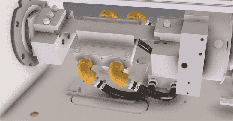
Fig. 24.7 High Density Gas Quench Head Assembly and Proportional Quench - DSI# 31730 and 59046.
The 59046 Proportional Quench is a variable flow rate quench system for use with the General-Purpose MCU - Strip Annealing Kit and uses a gas quench medium. This device allows for automatic flow rate adjustment based on the error between a user-programmed temperature profile and the actual specimen temperature.
| Characteristic | Specification |
|---|---|
| Type | Proportional Control Quenching Valve |
| Control Mode | Temperature Feedback with Programmable Gain |
| Quenching Medium | Independent Compressed Air or Inert Gas Source |
| Maximum Supply Pressure | 10 bar (145 psi) |
| Supply Line Size Minimum Diameter | 19 mm (0.75 in) |
| Supply Flow Rate Minimum | 4,000 L/min (1,057 gal/min) |
| Flow Range | 0 - 4,000 L/min (0 - 1,057 gal/min) |
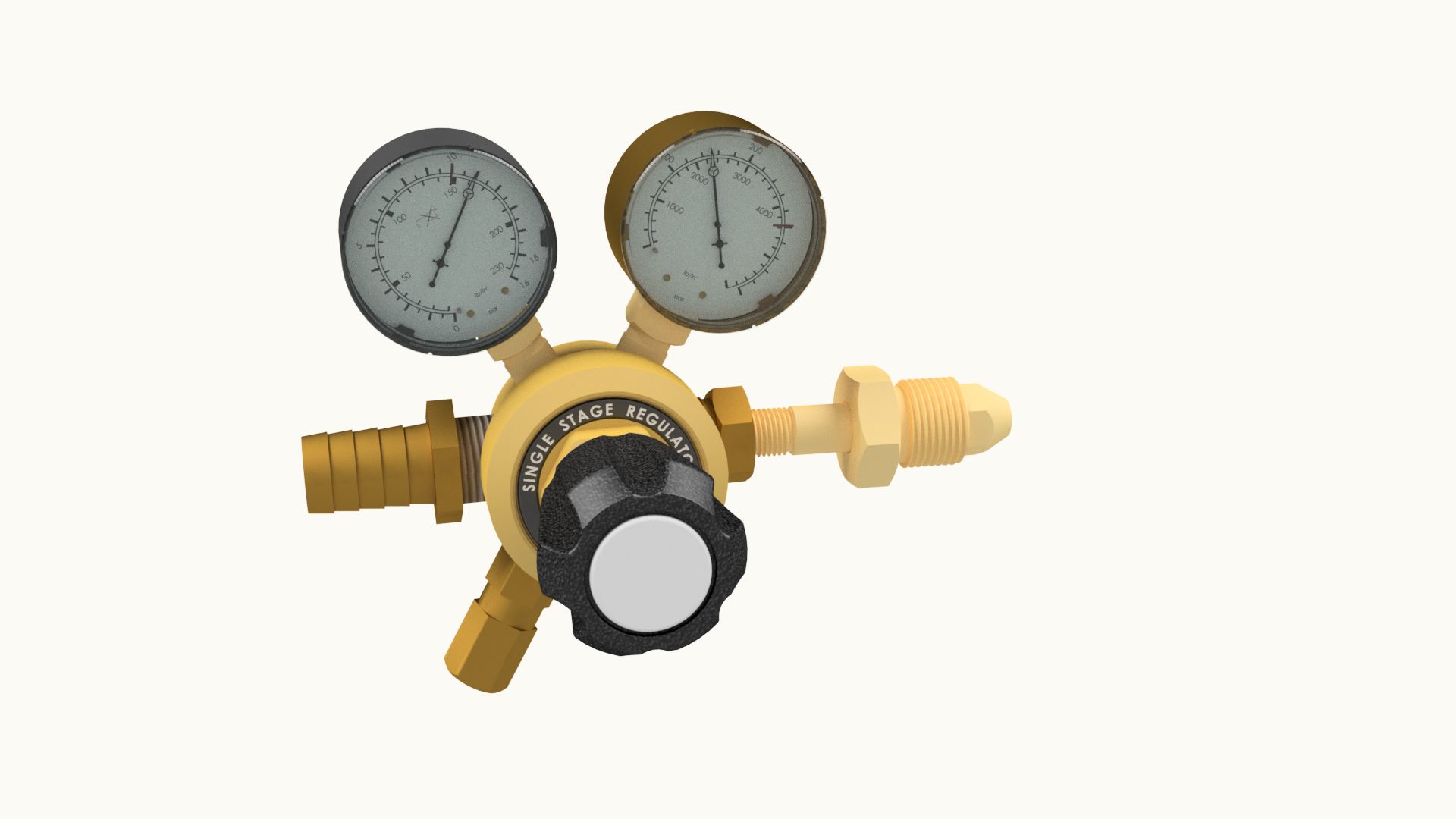
Fig. 24.8 Regulator - High Flow - DSI# 38525-TX.
| Part Number | Description | Sold As |
|---|---|---|
| 59046 | Proportional Quench - 3500 and 3800 GTC systems | Kit |
| 31731 | Proportional Quench - Series 3 systems | Kit |
| Required Accessories | ||
| 31730 | High-Density Gas Quench Head Assembly | Kit |
| 59025 | Accessory Instrument Module - GTC Systems only | |
| Optional Accessories | ||
| 38525-TX | Regulator - High Flow with Adapter Fittings - Country Specific | Ea. |
Note
Contact a DSI Sales Representative for specific part numbers for Regulator- High Flow - Adapter Fittings information.
24.2.1.6. Cryogenic Quench System
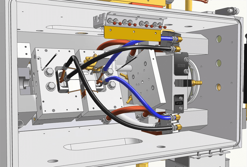
Fig. 24.9 Cryogenic Quench System - DSI# 59074.
The 59074 Cryogenic Quench System is designed to cool specimens to a cryogenic temperature range. This is typically achieved by using liquid nitrogen, although the system can also use liquid argon or other cryogenic gases. The system can also utilize an inert gas stream cooled in a bath of cryogenic fluid. In typical operation, the liquid nitrogen contacts the sample internally, similar to the action of the Closed ISO-Q Quench Kits. This quench medium delivery method ensures that an isothermal plane is maintained in the center of the specimen so that thermal gradients do not adversely affect dilatometry or microstructure analysis. The goal of the sub-zero quench is not to accelerate the quench rate, but rather to provide a means to reach cryogenic end-of-quench temperatures. Such endpoint temperatures are not achievable with DSI’s standard quenching systems.
Any temperature between the lowest achievable cryogenic temperature and room temperature can be achieved by using the Cryogenic Quench. Through control of the cryogenic quenching medium, plus the use of a technique called “back heating,” the Gleeble system is able to reach and maintain the programmed temperature. Back heating is the combined use of direct resistance heating and active quenching of a specimen at the same time.
Cooling specimens into a cryogenic temperature range is useful for studies evaluating the properties of materials at low temperatures, and for the evaluation of transformations that may occur below room temperature, such as evaluating the volume fraction and stability of retained austenite in highly alloyed tool steels, or retained austenite steels such as TRIP or Q and P steels.
Performance
Maximum (average) cooling rates listed below are for a 1018 carbon steel ISO-Q specimen SMR201B. The specimen was pre-chilled by flowing LN2 through the sample at a delivery pressure of 22 psi for 5 minutes. The specimen was held in Stainless Steel Hot Grips in a Low-Force Pocket Jaw Assembly.
| Specimen Type | Free Span | Drawing Number | Temperature Range | Cooling Rate |
|---|---|---|---|---|
| °C (°F) | °C/s (°F/s) | |||
| 10 mm dia x 84 mm long with reduced center | 5 mm dia x 5 mm long | SMR201B | 1,000 to 600 (1,832 to 1,112) | 60 (108) |
| 600 to 400 (1,112 to 752) | 60 (108) | |||
| 400 to 25 (752 to 77) | 40 (72) | |||
| 25 to -150 (77 to -238) | 10 (18) | |||
Note
Vacuum seals may be adversely affected by cryogenic temperatures.
System Recommendations
| Characteristic | Specification |
|---|---|
| Required Minimum Liquid Nitrogen Delivery Pressure | 1.51 bar (22 psi) |
| Maximum Liquid Nitrogen Delivery Pressure | 3.45 bar (50 psi) |
| Recommended Liquid Nitrogen Tank Volume | 230 L (60.75 gal) |
| Recommended System Pre-chill Recommended Duration for Maximum Cooling Rate | 5 min |
| Supplied Liquid Nitrogen Transfer Hose | 2 m (6 ft) long, female to female CGA-295 |
Note
The required fitting (connection) on a customer-supplied Cryogenic Liquid Container (CLC) must be a male CGA-295 (3/4-16 in UNF-2A-RH-EXT) (1/2 in SAE Flare). This fitting will enable the DSI-supplied Liquid Nitrogen Transfer Hose to connect to the CLC.
Note
Liquid nitrogen tank (Cryogenic Liquid Container, CLC) pressure is set with a pressure relief valve on the CLC. Note: A CLC setup with a 1.51 bar (22 psi) pressure relief valve has a set point for a maximum of 1.51 bar (22 psi)
Note
When pre-chilling the system while holding a sample at an elevated temperature, a 6-minute pre-chill is recommended.
Note
3.45 bar (50 psi) is not required for usage.
| Part Number | Description | Sold As |
|---|---|---|
| 59074 | Cryogenic Quench System | Kit |
| Required Accessories | ||
| 59025 | Accessory Instrument Module - GTC Systems only | |
24.2.2. 500 Series Quench Nozzle Kits
24.2.2.1. 500 Series Standard Quench Nozzle
The 59024 Standard Quench Nozzle provides the Gleeble 500 Series system with the ability to spray a quench medium directly onto the surface of a specimen for an increased cooling rates.
| Part Number | Description | Sold As |
|---|---|---|
| 59024 | Standard Quench Nozzle - 563 and 540 | Kit |
24.2.2.2. 500 Series ISO-Q Adapter
The 59023 500 Series ISO-Q Adapter provides the Gleeble system with the ability to quench a specimen internally, in a closed quench-fluid loop that never enters the testing chamber. The ISO-Q Adapter therefore allows for rapid cooling rates while the desired vacuum atmosphere is maintained. The ISO-Q Quench Nozzles are embedded in the specimen, and quench the specimen by direct contact. The specimens for use with the ISO-Q quench system have holes in each end to accommodate the ISO-Q Quench Nozzles. This allows the quench medium to contact the specimen internally. When using this method of quenching a vacuum or inert gas atmosphere can be maintained. This quench kit is typically used for Continuous Cooling Transformation (CCT) and Heat Affected Zone (HAZ) studies. The ISO-Q Quench System is sometimes referred to as a “closed quench” system.
| Part Number | Description | Sold As |
|---|---|---|
| 59023 | ISO-Q Quench Adapter - 563 and 540 | Kit |
24.3. Gleeble System Quench Cooling Rates
Quench cooling rates can be found in each system’s specifications section.