17. Low-Force Testing Systems
Materials developers are often faced with the task of eliminating cracking during rolling, casting, continuous casting, and welding processes. The possibility of cracking is greatly reduced if the range between the material’s nil-strength and nil-ductility temperatures are minimized. However, standard thermal-mechanical testing machines are often unable to control and apply the very small tensile forces required for nil-strength temperature (NST) testing. The Gleeble Low-Force Testing System, available for most Gleeble systems, create the conditions necessary for achieving accurate and reproducible NST values. Gleeble low-force systems are also capable of measuring low-forces in tension or compression.
The Low-Force Pocket Jaws are also useful for certain types of unrestrained thermal fatigue testing as they reduce the frictional resistance of the hydraulic system during thermal expansion on the specimen. CCT testing, with a crosswise dilatometer is commonly performed with the low-force testing system.
The Gleeble Low-Force Testing System consists of the Low-Force Carrier, Low-Force Pocket Jaws or Nil-Strength Jaws, and an optional Low-Force Load Cell.
17.1. Low-Force Carrier
The 9510-002 Low-Force Jaw Carrier is for use with all low-force testing configurations in the Gleeble 3500 and 3800 systems. The Jaw Carrier is the assembly upon which the Nil-Strength Jaws or Low-Force Pocket Jaws are mounted. The Jaw Carrier must be installed to use either jaw sets. sets. The Jaw Carrier must also be installed to mount the Low-Force Load Cell.
The low friction coefficient derived by the bearing system used in the Low-Force Jaw Carrier significantly reduces any external mechanical force experienced by a specimen during thermal expansion. The reduction in external mechanical forces ensures that the specimen can thermally expand free from any resistance of the hydraulic system.
Warning
Operating the Low-Force Carrier assembly with a specimen larger than recommended, or at a heating rate faster than recommended, can cause damage to the carrier’s heating cables. See Low-Force Pocket Jaws - Heating Rate or Nil-Strength Jaws - Heating Rate for heating specifications.
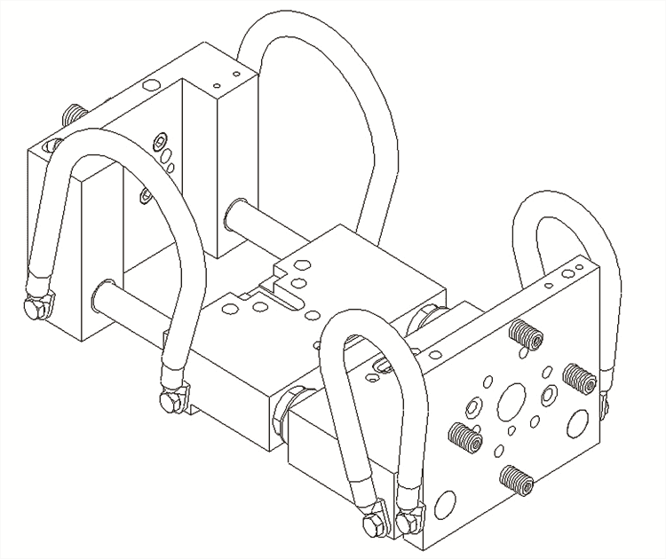
Fig. 17.1 Low-Force Carrier - DSI# 9510-002.
| Part Number | Description | Sold As |
|---|---|---|
| 9510-002 | Jaw Carrier Kit - Gleeble 3500 and 3800 | Kit |
17.2. Low-Force Pocket Jaws
The 9510-101 Low-Force Pocket Jaws can be used for low-force tension and compression testing. CCT dilatometery testing is also conducted with the Low-Force Pocket Jaws. The Pocket Jaw assemblies must be installed on the Low-Force Carrier and, are used with Gleeble Grips. The Low-Force Pocket Jaws are only available for Gleeble 3500 and 3800 systems.
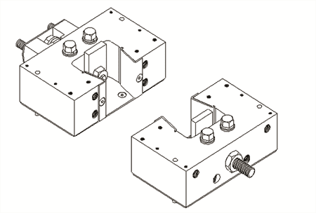
Fig. 17.2 Low-Force Pocket Jaws - DSI# 9510-101.
| Part Number | Description | Sold As |
|---|---|---|
| 9510-101 | Low-Force Pocket Jaw Assembly | Kit |
17.2.1. Jaw Rotation Kit
Low-Force Pocket Jaw Rotation Kit
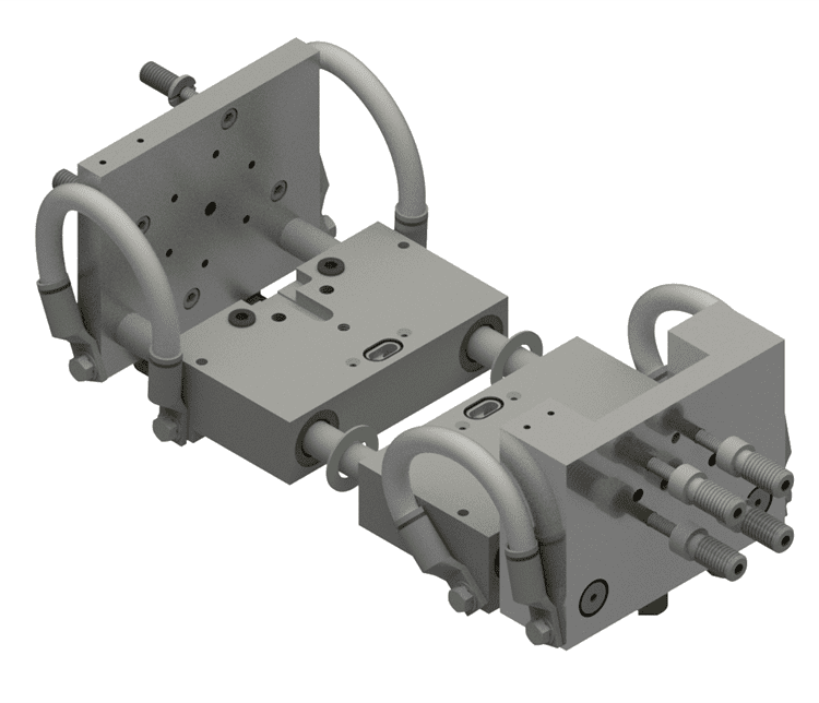
Fig. 17.3 Low-Force Pocket Jaws Rotation Kit - DSI# 9510-005.
The 9510-005 Low-Force Pocket Jaws Rotation Kit contains the parts necessary to rotate the pocket jaws 90 degrees. Specimens will now be mounted parallel to the vacuum tank doors. When used with standard grips devices such as DIC cameras, optical micrometers, pyrometers, or lasers will have a direct line of sight to the flat plane of the specimen. Viewing angles can be from either the front or back door vacuum tank windows.
| Part Number | Description | Sold As |
|---|---|---|
| 9510-005 | Low-Force Pocket Jaws - Jaw Rotation Kit | Ea. |
17.2.2. Low-Force Pocket Jaws - Heating Rate
Heating rates are based on using full contact copper grips and 1018 carbon steel or 6061 aluminum specimens in the Low-Force Pocket Jaws. See Gleeble Grips for more information regarding the selection of grips.
| Material | Specimen Size | Drawing Number | Maximum Heating Rate |
|---|---|---|---|
| °C/s (°F/s) | |||
| Steel Bar | 10 mm dia x 71 mm long | SMR009B | 25 (45) |
| Steel Bar | 10 mm square x 71 mm long | SMS004B | 25 (45) |
| Aluminum Bar | 6 mm dia x 71 mm long | SMR002A | 15 (27) |
| Steel Sheet | 1 mm thick x 25 mm wide x 26 mm long | SMF128B | 25 (45) |
| Aluminum Sheet | 1 mm thick x 25 mm wide x 26 mm long | SMF128A | 15 (27) |
17.2.3. Specimen Size Considerations
Gleeble systems are capable of testing a wide variety of material compositions and specimen geometries. Inherent limitations of the system, such as distance between the jaw or anvil faces, the maximum or minimum stroke speed, test temperature, and force limitations for the individual system must be considered when selecting a specific specimen geometry.
The target temperature of a test will also impact the size of a specimen that can safely be tested with a Gleeble system. For example, when considering a standard uniaxial compression specimen, it is possible for a soft material such as aluminum or copper to be tested at ambient temperature. Harder materials, such as steel or titanium alloys, are expected to be tested at elevated temperatures.
| Popular Specimen Sizes | ||
|---|---|---|
| Specimen Length | Specimen Width | Drawing Number |
| Bar Specimens | ||
| 116 mm | 6 mm dia | SMR104 |
| 71 mm | 10 mm dia | SMR009 |
| 71 mm | 10 mm2 | SMS004 |
To achieve the best thermal control, flat specimens should have a cross-sectional area between 25 mm2 and 400 mm2 (0.0387 in2 and 0.620 in2).
Warning
Operating the Low-Force Carrier assembly with a specimen larger than recommended, or at a heating rate faster than recommended, can cause damage to the carrier’s heating cables. See Low-Force Pocket Jaws - Heating Rate or Nil-Strength Jaws - Heating Rate for heating specifications.
17.3. Nil-Strength Jaws
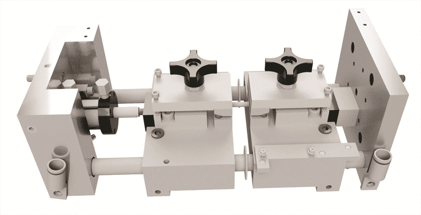
Fig. 17.4 Nil-Strength Jaw Configuration - DSI# 9510-051.
The Nil-Strength Jaw Set includes the grip mounting assembly and a pneumatic cylinder for applying static low-force loads. In the Nil-Strength Jaw Set, a pneumatic pneumatic cylinder provides the tensile force instead of the more powerful hydraulic system, thus allowing the application of small loads. Only a single load value can be applied during each test. This jaw configuration is intended for static force testing only.
| Characteristic | Specification |
|---|---|
| Air Cylinder Travel Range | ±25 mm (±0.98 in) |
| Air Cylinder Stroke-Rate Control | None |
| Part Number | Description | Sold As |
|---|---|---|
| 9510-051 | Nil-Strength Testing Assembly - 3500 and 3800 | Kit |
| 9510-052 | Nil-Strength Testing Assembly - 3180 | Kit |
17.3.1. Nil-Strength Jaws - Heating Rate
Heating rates are based on using full contact copper grips, and 1018 carbon steel specimens or 6061/T6 aluminum in the Nil-Strength Jaws. See Gleeble Grips for more information regarding the selection of grips.
| Material | Specimen Size | Drawing Number | Maximum Heating Rate |
|---|---|---|---|
| °C/s (°F/s) | |||
| Steel Bar | 6 mm dia x 81 mm long | SMR004B | 30 (54) |
| Aluminum Bar | 6 mm dia x 81 mm long | SMR004A | 15 (27) |
| Steel Sheet | 1 mm thick x 25 mm wide x 26 mm long | SMF128B | 25 (45) |
| Aluminum Sheet | 1 mm thick x 25 mm wide x 26 mm long | SMF128A | 15 (27) |
17.3.2. Specimen Size Considerations
Gleeble systems are capable of testing a wide variety of material compositions and specimen geometries. Inherent limitations of the system, such as distance between the jaw or anvil faces, the maximum or minimum stroke speed, test temperature, and force limitations for the individual system must be considered when selecting a specific specimen geometry.
The target temperature of a test will also impact the size of a specimen that can safely be tested with a Gleeble system. For example, when considering a standard uniaxial compression specimen, it is possible for a soft material such as aluminum or copper to be tested at ambient temperature. Harder materials, such as steel or titanium alloys, are expected to be tested at elevated temperatures.
| Popular Specimen Sizes | |||
|---|---|---|---|
| Specimen Length | Specimen Width | Specimen Thickness | Drawing Number |
| Bar Specimens | |||
| 81 mm | 6 mm dia | N/A | SMR004 |
| 26 mm | 25 mm | 1 mm | SMF128 |
Warning
Operating the Low-Force Carrier assembly with a specimen larger than recommended, or at a heating rate faster than recommended, can cause damage to the carrier’s heating cables. See Low-Force Pocket Jaws - Heating Rate or Nil-Strength Jaws - Heating Rate for heating specifications.
17.3.3. Nil-Strength Grips
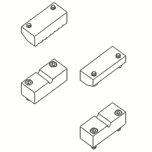
Fig. 17.5 Nil-Strength Grips - DSI# 9510-051.
The Nil-Strength Jaw set requires at least one set of grips. Each grip set contains two stainless steel top grips and two copper bottom grips.
| Part Number | Description | Sold As |
|---|---|---|
| 9510-063 | Nil-Strength Grip Set - 6 mm square specimens | Set |
| 9510-060 | Nil-Strength Grip Set - 6 mm dia round specimens | Set |
| 9510-061 | Nil-Strength Grip Set - 1/4 in dia round specimens | Set |
| 9510-062 | Nil-Strength Grip Set - flat specimens | Set |
17.4. Low-Force Load Cells
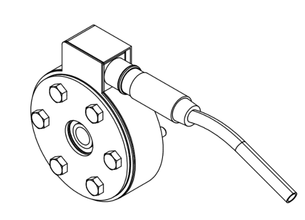
Fig. 17.6 Low-Force Load Cell - 3500 - DSI# 9510-120.
When mounted to the Low-Force Jaw Carrier, a Gleeble Low-Force Load Cell will provide improved accuracy at low-forces. There is no mechanical overload protection for these load cells. Due to the high-speed of the hydro-mechanical capabilities of a Gleeble system, these load cells can inadvertently be damaged. This damage can occur even when utilizing the software load-limiting capabilities of QuikSim2. Each load cell is supplied as an assembly that includes the mounting hardware, a magnetic shield, and a load cell signal conditioner.
| Characteristic | Specification |
|---|---|
| Maximum Load | 2,268 kgf (5,000 lbf) 22.24 kN |
| Non-linearity | ±0.1 % of full scale |
| Hysteresis | ±0.08 % of full scale |
| Non-Repeatability | ±0.03 % of full scale |
| Overload rating | 150 % of capacity |
| Deflection - Full Scale | 0.0508 mm (0.002 in) |
| Force Measurement Accuracy | ±1.0 % of full scale |
| Force Measurement Resolution | ±1 kgf (2.2 lbf) |
| Part Number | Description | Sold As |
|---|---|---|
| 3500 Low-Force Load Cell | ||
| 9510-120 | 500 to 5,000 lbf Load Cell - Gleeble 3500 | Kit |
| LC05000 | Replacement 3500 Low-Force Load Cell - Load Cell Only | Ea. |
| 3800 Low-Force Load Cell | ||
| 9510-121 | 500 to 5,000 lbf Load Cell - Gleeble 3800 | Kit |
| LC05000B | Replacement 3800 Low-Force Load Cell - Load Cell Only | Ea. |
17.5. Low-Force Assemblies - Replacement Parts
Low-Force Carrier
| Part Number | Description | Sold As |
|---|---|---|
| HH251 | Moving-Side Mounting Hardware - 5/16-18 x 1 1/4 in SHCS S.S. | Ea. |
| 9510-228 | Moving-Side Bolt-Adapter - 1/2-13 to 5/16-18 | Ea. |
| HH245 | Fixed-Side Mounting Hardware - 5/16-18 x 1 in SHCS S.S. | Ea. |
| 9510-229 | Fixed-Side Bolt-Adapter - 1/2-13 to 5/16-18 | Ea. |
| ORS014 | Fixed-Side O-Rings | Ea. |
| OR7017 | Jaw Mount O-Ring | Ea. |
| 9510-010 | Carrier Heating Cable - 14.0 inch length | Ea. |
| 9510-011 | Carrier Heating Cable - 10.4 inch length | Ea. |
Low-Force Pocket Jaws
| Part Number | Description | Sold As |
|---|---|---|
| 9510-407 | Wear Plate - Copper | Ea. |
| HE115 | Wear Plate Installation Hardware - 10-32 x 3/8 in FHSHCS S.S. | |
| 9510-416 | Jaw-Jack Bolt | Ea. |
| HE305A | Jaw-Jack Bolt Extension 10-32 x 1/4 in SHCS S.S. | Ea. |
| 9510-428 | Pocket Jaw 3/8 in Jack-Plate | Ea. |
| HY069 | Repair Helicoil - Jack Bolt Threading | Ea. |
| 9510-414 | Water Stop Plug | Ea. |
| OR7016 | Jaw-Plate O-Rings | Ea. |
Low-Force Load Cells
| Part Number | Description | Sold As |
|---|---|---|
| HG135 | Load Cell Mounting Hardware - 1/4-20 x 1 3/4 in HHB S.S. | Ea. |
| HK595 | 1/2-20 x 2 in Load Cell to Jaws Bolt | Ea. |
| BRS0250D | 5/16 in OD IGUS Sleeve Bearing | Ea. |
| HG042 | 1/2 in OD Plastic Spacer | Ea. |
Nil-Strength Jaws
| Part Number | Description | Sold As |
|---|---|---|
| 9510-205 | Cylinder Mounting Blocks | Ea. |
| HG361 | Cylinder Mounting Block Installation Hardware - 1/2-20 x 1/2 in SHCS S.S. | Ea. |