6. Mobile Conversion Units
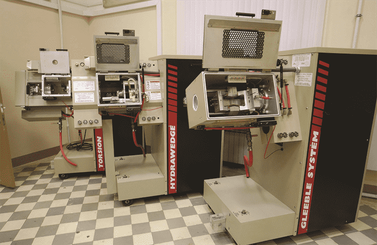
Fig. 6.1 MCUs Offered for a Gleeble System - Left to Right: Hot Torsion, Hydrawedge II, General-Purpose MCU.
Mobile Conversion Units (MCUs), available for the Gleeble 3500C and 3800, provide researchers with additional application-specific capabilities. While the General-Purpose MCU comes standard on most systems, additional available MCUs include the Hydrawedge II, MAXStrain II, Hot Torsion, Large-Sample Strip Annealing, and High-Temperature systems.
Mobile Conversion Units feature a rolling frame design enabling easy installation onto a Gleeble Load Unit. The wheeled fram of the MCU allows for quick and simple MCU changes providing a much wider range of testing capabilities. Changing the MCU eliminates the need to purchase separate stand-alone systems.
Note
Mobile Conversion Units are not compatible with Gleeble 3180, 3500-GTC Pedestal, or 500 Series systems.
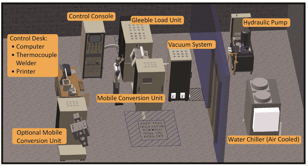
Fig. 6.2 Typical Design of a Gleeble 3800 or 3500C Lab with Two MCUs Supplied.
6.1. General-Purpose Mobile Conversion Unit
Capable of conducting tension and compression tests, the General-Purpose Mobile Conversion Unit (MCU) (often referred to as a “Pocket Jaw”) provides the most versatile platform for the performance of a wide variety of simulations and tests. General thermal and mechanical specifications of a Gleeble 3500-GTC or a Gleeble 3800-GTC are measured while utilizing a General-Purpose MCU installed on the Load Unit. The General=Purpose MCU is supplied by default with these systems.
- High-Temperature Testing Limitations:
- The General-Purpose MCU heating system can achieve temperatures up to the melting point of many materials. However at any temperature above 1,700°C (3,092°F) the vacuum tank and other instrumentation components may be damaged due to excessive radiant heat. Short-duration tests on small specimens may be conducted above 1,700°C (3,092°F) in a General-Purpose MCU. However DSI offers a High Temperature Testing Upgrade Kit that includes enhanced cooling and capabilities that are optimized for higher temperature testing. For tests requiring temperatures above 1,700°C (3,092°F), contact a DSI Engineer to discuss capabilities and limitations.
| Part Number | Description | Sold As |
|---|---|---|
| 35010 | General-Purpose MCU for Gleeble 3500C | Ea. |
| 35012 | General-Purpose MCU for Gleeble 3800 | Ea. |
6.1.1. Upgrade Kits - General-Purpose Mobile Conversion Unit
High Temperature Testing Upgrade Kit
The High Temperature Testing Upgrade Kit includes modifications to the standard 3500 and 3800 General Purpose Mobile Conversion Units to increase the maximum sustained temperature that can be safely achieved in the vacuum tank. With the upgrade kit installed, standard specimens can be tested at temperatures up to 3,000°C (5,432°F) for extended periods of time.
The kit includes equipment to cool and protect key systems in the Gleeble, including reinforced and actively cooled tank windows, modified cooling lines, quick-connect fittings and a heat exchanger to protect the thermocouple cold junction box. Note that during installation of the upgrade kit, the front and rear standard windows are replaced with smaller windows, therefore operator visibility will be limited and some measurement systems such as Digital Image Correlation and video recording devices are not compatible with the High Temperature Testing Upgrade Kit.
Standard windows can be reinstalled to allow for usage of these devices. The heat exchanger for the thermocouple cold junction box can remain installed as it does not interfere with existing measurement devices.
Usage of a Pyrometer Control Camera (sold separately) is recommended to measure and control temperature of the specimen. DSI offers a series of pyrometers that have been optimized for specific temperature ranges.
| Part Number | Description | Sold As |
|---|---|---|
| 35055 | High Temperature Testing Upgrade Kit - 3800 or 3500 General Purpose MCU | Ea. |
Single Sided Heating
The Single Sided Heating kit allows the Gleeble system to heat a specimen from below. A radiative heating element is installed between the jaws redirecting the path of electrical current away from the specimen. This new electrical path ensures the specimen is heated only due to the radiation from the element. The Single Sided Heating kit is designed to perform thermal testing only, the Gleeble’s mechanical deformation capabilities are limited.
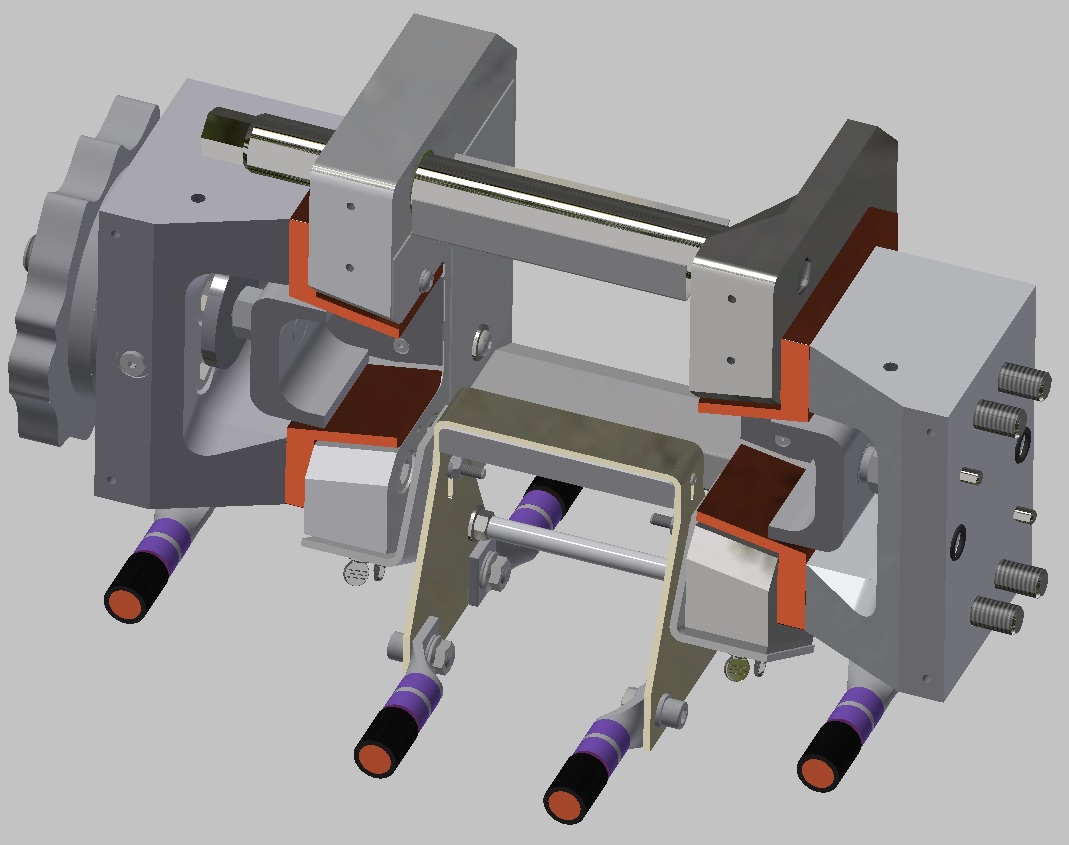
Fig. 6.3 Single Sided Heating Kit DSI # 37243
| Part Number | Description | Sold As |
|---|---|---|
| 37243 | Single Sided Heating Kit - 3800 or 3500 General Purpose MCU | Ea. |
General-Purpose MCU Pocket Jaw Rotation Kit
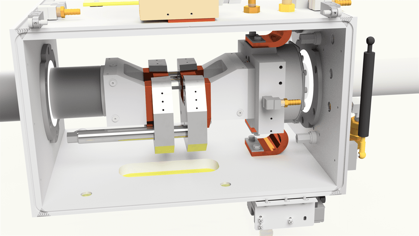
Fig. 6.4 General-Purpose MCU Pocket Jaw Rotation Kit - DSI# 37500.
The 37500 General-Purpose MCU - Pocket Jaw Rotation Kit contains the parts necessary to rotate the pocket jaws 90 degrees. After rotating the specimens, the face of the specimen will now be parallel to the vacuum tank doors. When used with standard grips devices such as DIC cameras, optical micrometers, pyrometers, or lasers will have a direct line of sight to the flat plane of the specimen. Viewing angles can be from either the front or back door vacuum tank windows.
| Part Number | Description | Sold As |
|---|---|---|
| 37500 | General-Purpose MCU - Pocket Jaw Rotation Kit | Ea. |
6.1.2. General-Purpose Jaws - Replacement Parts
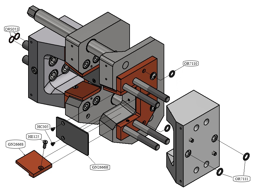
Fig. 6.5 Pocket Jaw Assembly.
| Part Number | Description | Sold As |
|---|---|---|
| GN2666S | Universal Wear Plates | Ea. |
| HE125 | Wear Plate Installation Hardware - 10-32 x 5/8 in FHSHCS S.S. | Ea. |
| GN2666H | Pocket Jaw Backing Plate | Ea. |
| HC305 | Backing Plate Installation Hardware - 6-30 x 1/4 in FHSHCS S.S. | Ea. |
| OR7110 | Inter-Jaw O-Ring | Ea. |
| OR7111 | Fixed Side Jaw O-Ring | Ea. |
| ORS013 | Moving Shaft O-Rings | Ea. |
| HZ020 | Moving Shaft Dowel Pin - 1/4 x 1/2 in | Ea. |
| HL072 | Moving Side Jaw Bolt - 5/8-11 x 2 1/2 in SHCS S.S. | Ea. |
| HK421 | Fixed Side Jaw Bolt - 1/2-13 x 5 in SHCS S.S. | Ea. |
| 32825 | Jaw Alignment Fixture Kit | Kit |
| GN2665D | Moving Side Jaw | Ea. |
| GN2665E | Fixed Side Jaw | Ea. |
| GN2872C | Flexible Copper Grounding Lead | Ea. |
| WIND010 | Vacuum Tank Door Window | Ea. |
6.1.3. MCU Dimensions
| Equipment | Height | Depth | Width | Weight |
|---|---|---|---|---|
| General-Purpose MCU for 3500C and 3800 | 158 cm (62 in) | 86 cm (34 in) | 157 cm (62 in) | 565 kg (1,245 lb) |
6.2. Hydrawedge II
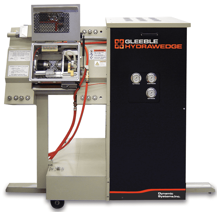
Fig. 6.6 Hydrawedge II MCU - DSI# 35034.
The Hydrawedge II Mobile Conversion Unit (MCU) has been developed for researchers who wish to optimize multiple-hit, high-speed deformations. Such as multi-stand rolling mills and multi-hit forging processes. The Hydrawedge II offers excellent physical simulation capabilities.
Available as an option for Gleeble 3800 and 3500C systems, the Hydrawedge II is the only commercially available machine that offers the capability to perform high-speed deformation simulations with completely independent control of both strain and strain rate. The Hydrawedge II is available for both the Gleeble 3800-GTC and the Gleeble 3500-GTC systems. This MCU is specifically built to match the Force capabilities of the Load Unit it was purchased to be paired with.
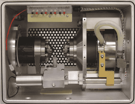
Fig. 6.7 Hydrawedge II MCU Vacuum Tank.
The Hydrawedge II control software, Hot Deformation Software (HDS), allows the system to be programmed with the same parameters as in a rolling mill schedule. The Hydrawedge II delivers test results without strain overshoot or strain rate deceleration, either one of which can reduce the accuracy of the simulation. Operators enter soak times and temperatures, rolling temperature, inter-pass time, controlled cooling time, strain rate, and amount of strain for each compressive movement. The software then calculates and programs the desired system movements that are needed to simulate the desired compression schedule on the Hydrawedge II.
When a system is equipped with a Hydrawedge II, deflection of the Gleeble system can occur. The unique design of the MCU allows it to compensate both for machine compliance and for thermal expansion of the compression anvils, delivering world-class accuracy.
The Hydrawedge II MCU is compatible with many optional accessories offered for the General-Purpose MCU. One of these options is the Gleeble Induction Heating System (IHS). The Hydrawedge II benefits immensely from the induction heating system, which creates a more uniform thermal gradient across a uniaxial compression specimen
Conducting Tests Using The Hydrawedge II MCU
For replacement anvil assemblies and consumables, see Uniaxial Compression Studies and Plane Strain Studies. See Hydrawedge II Lengthwise Strain Gauge - Range: ±25.4 mm for specifications for the Hydrawedge II Jaw strain transducer.
| Part Number | Description | Sold As |
|---|---|---|
| 35033 | Hydrawedge II MCU for Gleeble 3500C | Ea. |
| 35034 | Hydrawedge II MCU for Gleeble 3800 | Ea. |
6.2.1. Hydro-Mechanical
The Hydrawedge II system is capable of multiple compressions at high strain rates, which allows the accurate replication of an entire hot rolling or multi-hit forging process — from reheating, through multiple stand rolling, to controlled cooling.
| Characteristic | Specification |
|---|---|
| Maximum Stroke Distance | 36 mm (1.417 in) |
| Maximum Stroke Rate | 330 mm/s (12.9 in/s) |
| Strain Control Range | 25.4 mm (1 in) |
| Maximum Recommended Strain Rate | 50/s |
| Maximum Compressive Force - Gleeble 3800 | 20,000 kgf (~44,000 lbf) (196 kN) |
| Maximum Compressive Force - Gleeble 3500C | 10,000 kgf (~22,000 lbf) (98 kN) |
Note
Accuracy is measured at a temperature of 23°C (73°F). Maximum stroke rates are at a hydraulic pressure of 203 bar (2,950 psi) ±3 % and an oil temperature of 30°C (86°F).
6.2.1.1. Load Cell
| Characteristic | Specification |
|---|---|
| Non-linearity | ±0.1 % of full scale |
| Hysteresis | ±0.08 % of full scale |
| Non-Repeatability (Maximum) | ±0.03 % of full scale |
| Overload Rating | 150 % of capacity |
| Deflection - Full Scale | 0.076 mm (0.003 in) |
| Force Measurement Accuracy | ±1.0 % of full scale |
| Force Measurement Resolution | ±1 kgf (2.2 lbf) |
Note
Accuracy is measured at a temperature of 23°C (73°F). Maximum stroke rates are at a hydraulic pressure of 203 bar (2,950 psi) ±3 % and an oil temperature of 30°C (86°F).
6.2.1.2. Hydrawedge II - Stroke Transducer
| Characteristic | Specification |
|---|---|
| Type | LVDT |
| Linear Range | ±18 mm (±0.7 in) |
| Linearity | ±0.25 % of full scale |
| Stroke Measurement Accuracy | ±0.5 % of full scale |
| Stroke Measurement Resolution | 0.002 mm (7.87-5 in) |
Note
Accuracy is measured at a temperature of 23°C (73°F). Maximum stroke rates are at a hydraulic pressure of 203 bar (2,950 psi) ±3 % and an oil temperature of 30°C (86°F).
6.2.2. Thermal Subsystem
Hydrawedge II MCUs can heat a specimen with the default direct resistance heating subsystem or an optional Gleeble Induction Heating System (IHS).
Direct resistance heating provides the ability to reproduce the wide variety of thermal profiles that materials undergo in actual processes. This is critical to the success of thermal-mechanical testing and physical simulation. All Gleeble systems have high-speed heating and cooling rates that can accurately replicate nearly any thermal profile required.
Induction heating is well-suited for use in uniaxial compression testing where it can provide a uniform temperature across the specimen from anvil to anvil. Induction heating can also be used in tensile testing, heat treating applications, and plane strain compression testing. Induction heating is also compatible for custom test setups due to the flexibility it offers.
The integration of the Gleeble Induction Heating System does not impact the functionality of the direct resistance heating capabilities. The Induction Heating System retains the performance standards researchers have come to know and expect from their Gleeble systems. Choosing between standard direct resistance heating and optional induction heating is available through the configuration mode of a GTC system. Only one heating method can be used per test.
| Characteristic | Specification |
|---|---|
| Heating System Type and Control | Direct resistance with closed-loop control |
| Temperature Range | Room Temperature to 1,700°C (3,092°F) |
| Direct Resistance Heating Sampling Rate | Twice the power line frequency (100 - 120 Hz) |
| Resolution | ±1°C or°F |
| Maximum Number of Thermal Channels | 4 thermocouple channels, or 2 thermocouple channels and 1 pyrometer channel |
| Accuracy of Control | ±1°C (in steady state) |
| Accuracy of Measurement | ±2°C or ±1 % of temperature (whichever is greater) plus the accuracy of the thermocouple wire (in steady state) |
Note
As the specimen size, diameter, length, or cross-sectional area increases the effective heating rate will decrease.
6.2.2.1. Resistance Heating Rates
Uniaxial Compression Sample Heating Rates
The maximum heating rates listed below are average rates for 1018 carbon steel specimens using 9219-062 Tungsten Carbide Anvil Caps, and resistance heating. See Uniaxial Compression Studies for more information regarding the selection of anvil caps and assemblies.
| Specimen | Drawing Number | Maximum Heating Rate |
|---|---|---|
| °C/s (°F/s) | ||
| 6 mm dia by 9 mm long | SMC206B | 20 (34) |
| 10 mm dia by 15 mm long | SMC203B | 5 (9) |
Plane Strain Sample Heating Rates
The maximum heating rates listed below are average rates for 1018 carbon steel specimens using 9105-252 Tungsten Carbide Plane Strain Anvils, and resistance heating. See Plane Strain Studies for more information regarding the selection of anvil caps and assemblies.
| Specimen | Drawing Number | Maximum Heating Rate |
|---|---|---|
| °C/s (°F/s) | ||
| 10 mm x 20 mm x 15 mm | SMC001B | 5 (6) |
| 30 mm x 30 mm x 30 mm | SMC010B | 2 (3.6) |
6.2.2.2. Induction Heating Rates
The maximum heating rates listed below are average rates for 1018 carbon steel specimens using a Gleeble Induction Heating System (IHS).
Uniaxial Compression Heating Rates
The maximum heating rates listed below are average rates for 1018 carbon steel specimens using 9219-378 Silicon Nitride Uniaxial Compression Anvils, and a Gleeble Induction Heating System (IHS). For more information regarding the selection of induction anvil caps and assemblies see Compression Kits.
| Specimen | Drawing Number | Maximum Heating Rate |
|---|---|---|
| °C/s (°F/s) | ||
| 6 mm dia by 9 mm long | SMC206B | 20 (36) |
| 10 mm dia by 15 mm long | SMC203B | 20 (36) |
| 15 mm dia by 22 mm long | SMC210B | 20 (36) |
Note
See Gleeble Induction Heating System (IHS) for specifications of the induction heater.
Plane Strain Heating Rates
The maximum heating rates listed below are average rates for 1018 carbon steel specimens using 9105-259 Extended Silicon Nitride Small Plane Strain Anvils, and a Gleeble Induction Heating System (IHS). For more information regarding the selection of induction anvil caps and assemblies see Compression Kits.
| Specimen | Drawing Number | Maximum Heating Rate |
|---|---|---|
| °C/s (°F/s) | ||
| 3 mm x 10 mm x 5 mm | SMC009B | 20 (36) |
| 10 mm x 20 mm x 15 mm | SMC001B | 20 (36) |
| 30 mm x 30 mm x 30 mm | SMC010B | 20 (36) |
Note
See Gleeble Induction Heating System (IHS) for specifications of the induction heater.
6.2.3. Cooling Rates
Uniaxial Compression Quenching Rates
The maximum cooling rates listed below are average rates for 1018 carbon steel specimens, water quenched, using a 59013 High Flow Quench system and a 31733 Hydrawedge II - Multi-Function Open Quench Spray Nozzle Kit. See Quench Systems for more information about quench kits and quench tanks.
| Specimen | Drawing Number | Temperature Range | Cooling Rate |
|---|---|---|---|
| °C (°F) | °C/s (°F/s) | ||
| 6 mm dia by 9 mm long | SMC206B | 1,000-500 (1,832-932) | 500 (900) |
| 10 mm dia by 15 mm long | SMC203B | 1,000-500 (1,832-932) | 300 (540) |
| 15 mm dia by 22 mm long | SMC210B | 1,000-500 (1,832-932) | 100 (180) |
Plane Strain Quenching Rates
The maximum cooling rates listed below are average rates for 1018 carbon steel specimens, water quenched, using a 59013 High Flow Quench system and a 31733 Hydrawedge II - Multi-Function Open Quench Spray Nozzle Kit. See Quench Systems for more information about quench kits and quench tanks.
| Specimen | Drawing Number | Temperature Range | Cooling Rate |
|---|---|---|---|
| °C (°F) | °C/s (°F/s) | ||
| 3mm x 10mm x 5mm | SMC009B | 1,000-300 (1,832-572) | 300 (540) |
| 10mm x 20mm x 15mm | SMC001B | 1,000-300 (1,832-572) | 200 (360) |
| 30mm x 30mm x 30mm | SMC010B | 1,000-300 (1,832-572) | 50 (90) |
6.2.4. Specimen Size Considerations
Gleeble systems are capable of testing a wide variety of material compositions and specimen geometries. Inherent limitations of the system, such as distance between the jaw or anvil faces, the maximum or minimum stroke speed, test temperature, and force limitations for the individual system must be considered when selecting a specific specimen geometry.
The target temperature of a test will also impact the size of a specimen that can safely be tested with a Gleeble system. For example, when considering a standard uniaxial compression specimen, it is possible for a soft material such as aluminum or copper to be tested at ambient temperature. Harder materials, such as steel or titanium alloys, are expected to be tested at elevated temperatures.
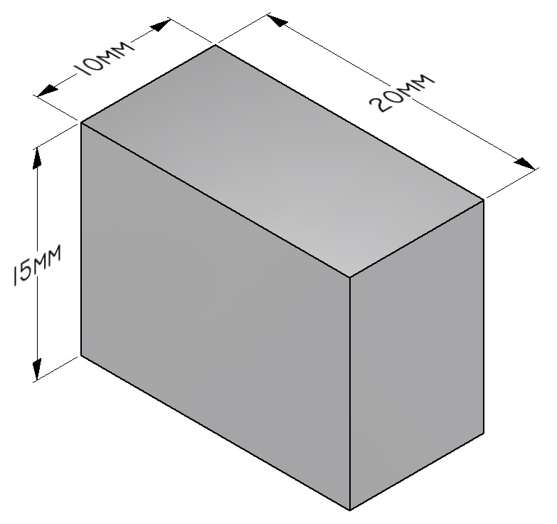
Fig. 6.8 Plane Strain Specimen - SMC001.
The uniaxial compression and plane strain compression tests conducted with the Hydrawedge II MCU are typically run on specific specimen geometries. These geometries have been uniquely selected for optimal performance, data reliability, and test functionality. Contact Dynamic Systems for assistance identifying a recommended specimen geometry.
| Popular Specimen Sizes | |||
|---|---|---|---|
| Specimen Length | Specimen Width | Specimen Thickness | Drawing Number |
| Uniaxial Compression | |||
| 9 mm | 6 mm dia | N/A | SMC206 |
| 12 mm | 8 mm dia | N/A | SMC200 |
| 15 mm | 10 mm dia | N/A | SMC203 |
| Plane Strain | |||
| 20 mm | 15 mm | 10 mm | SMC001 |
| 35 mm | 25 mm | 15 mm | SMC007 |
6.2.5. MCU Dimensions
| Equipment | Height | Depth | Width | Weight |
|---|---|---|---|---|
| Hydrawedge II MCU | 158 cm (62 in) | 84 cm (33 in) | 150 cm (59 in) | 885.8 kg (1,953 lb) |
6.2.6. Hydrawedge II Lengthwise Strain Gauge - Range: ±25.4 mm
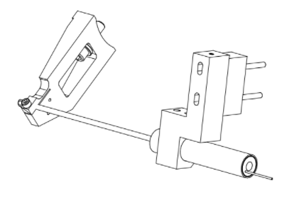
Fig. 6.9 Hydrawedge II Lengthwise Strain Gauge - DSI# 39057.
The 39055 Hydrawedge L-Strain System is designed specifically to be mounted in the Hydrawedge II MCU.
| Characteristic | Specification |
|---|---|
| Type | LVDT |
| Linear Range | ±25.4 mm (1.0 in) |
| Linearity | ±0.25 % of full scale over ±25.4 mm (±1.0 in) |
| Resolution | ±2 μm (7.87 x 10⁻⁵ in) |
| Gauge Length | 0 to 31 mm (0 to 1.22 in) |
| Maximum Usable Stroke Rate | 2,000 mm/s (78.74 in/s) |
| Maximum Recommended Strain Rate | 50/s |
Note
The effective maximum strain rate is dependent on the specimen material, size, and test temperature.
| Part Number | Description | Sold As |
|---|---|---|
| 39057 | Hydrawedge II Lengthwise Strain Gauge - Kit and Module included | Kit |
| Replacement Parts | ||
| TRN006 | 6 inch LVDT Stroke Transducer | Ea. |
| TRN006A | Measurement Core for TRN006 | Ea. |
| TRN006B | Measurement Core Bushing for TRN006 | Ea. |
6.3. Hot Torsion
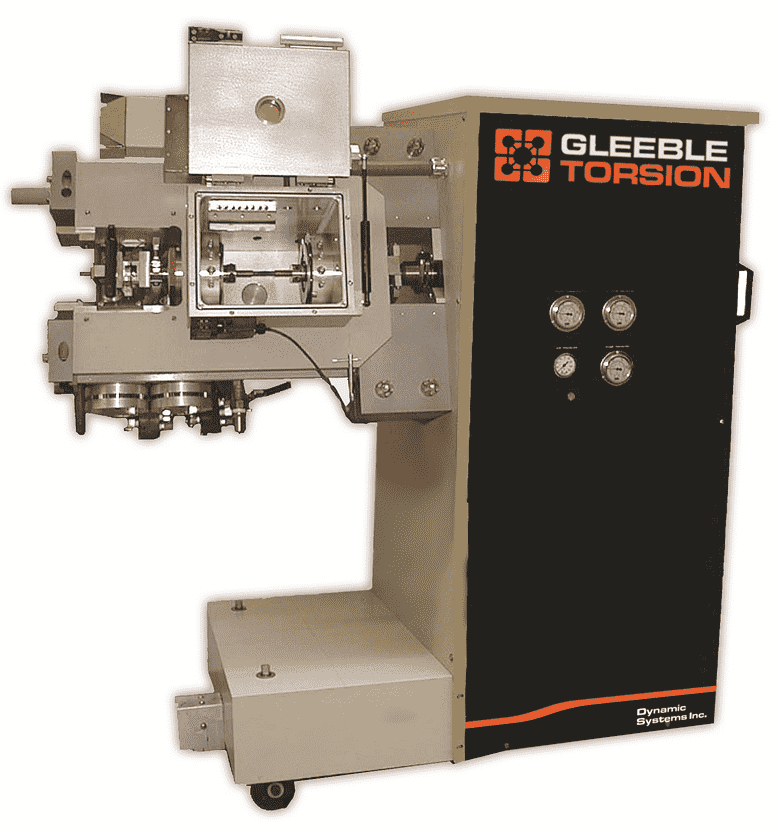
Fig. 6.10 Hot Torsion MCU - DSI# 35050.
The Hot Torsion MCU is available for both the Gleeble 3500-GTC or the Gleeble 3800-GTC systems.
The Hot Torsion Mobile Conversion Unit (MCU) adds world-class hot torsion testing capability to Gleeble 3500C and 3800 systems. Hot Torsion Systems from Dynamic Systems are the first commercially available torsion systems to incorporate direct resistance heating.
This torsion system is mounted on the roll-on/roll-off MCU design available with Gleeble 3500 and 3800 systems. With this unique design, the torsion hydraulics, electronics, vacuum tank, jaws, grips and load cell are all contained within a single MCU. This MCU can easily be connected and disconnected from the Gleeble load frame. This simplifies changeover from one major testing function to another. In a short period of time a Gleeble can be changed from hot compression testing to hot torsion testing. The Gleeble computer control automatically senses when a Hot Torsion MCU is attached and reconfigures the computer and electronics for hot torsion testing.
| Part Number | Description | Sold As |
|---|---|---|
| 35050 | Hot Torsion MCU for Gleeble 3500C and 3800 | Ea. |
6.3.1. Hydro-Mechanical
The Hot Torsion MCU can be programmed for a partial revolution or multiple revolutions. Researchers can choose between radians, revolutions, or degrees of rotation as their preferred unit of angular measurement.
| Characteristic | Specification |
|---|---|
| Motor Drive | Hydraulic Servo Actuator |
| Revolution Control | Computer-controlled |
| Maximum Thrust in Tension | 500 kgf (1,102.31 lbf) 4.9 kN |
| Maximum Thrust in Compression | 500 kgf (1,102.31 lbf) 4.9 kN |
| Maximum Torque | 50 Nm (36.85 lbf/ft) with standard torque cell |
| 100 Nm (+ 73.75 lbf/ft) with optional torque cell | |
| Angular Resolution | ±0.1 degree |
| Maximum Number of Revolutions | 90 |
| Minimum Control Speed | 2 rpm |
| Maximum Control Speed | 1,500 rpm for 1 second |
| Maximum Acceleration | 0 - 1,500 rpm in 7 ms |
| Maximum Deceleration | 1,500 - 0 rpm in 7 ms |
Note
Maximum acceleration and deceleration are specified under no load.
Note
For bidirectional torsion testing Contact Dynamic Systems for more information.
Note
Accuracy is measured at a temperature of 23°C (73°F). Maximum stroke rates are at a hydraulic pressure of 203 bar (2,950 psi) ±3 % and an oil temperature of 30°C (86°F).
6.3.1.1. Thrust Cell
The thurst cell measures lateral forces imparted to the specimen. The thrust cell load train can be uncoupled from the main hydraulics of the Gleeble system through a 550 kgf protective shear pin. The load train can be adjusted manually or mechanically to load or unload specimens.
| Characteristic | Specification |
|---|---|
| Non-linearity | ±0.1 % of full scale |
| Hysteresis | ±0.08 % of full scale |
| Non-Repeatability (Maximum) | ±0.05 % of full scale |
| Overload Rating | 150 % of capacity |
| Deflection - Full Scale | 0.076 mm (0.003 in) |
| Force Measurement Accuracy | ±1.0 % of full scale |
| Force Measurement Resolution | ±1 kgf (2.2 lbf) |
Note
Accuracy is measured at a temperature of 23°C (73°F). Maximum stroke rates are at a hydraulic pressure of 203 bar (2,950 psi) ±3 % and an oil temperature of 30°C (86°F).
6.3.1.2. Torque Cell
The torque cell of the Hot Torsion MCU measures the clockwise rotational forces experienced by a specimen. The torsional forces measured by the torque cell are then are then converted into strain values.
| Characteristic | Specification |
|---|---|
| Non-linearity | ±0.1 % of full scale |
| Hysteresis | ±0.08 % of full scale |
| Non-Repeatability (Maximum) | ±0.05 % of full scale |
| Overload Rating | 150 % of capacity |
| Deflection - Full Scale | 0.076 mm (0.003 in) |
| Torque Measurement Accuracy | ±1.0 % of full scale |
| Torque Measurement Resolution | ±1 Nm (0.73 lbf/ft) |
Note
Accuracy is measured at a temperature of 23°C (73°F). Maximum stroke rates are at a hydraulic pressure of 203 bar (2,950 psi) ±3 % and an oil temperature of 30°C (86°F).
6.3.2. Thermal Subsystem
The Hot Torsion MCU heats specimens using direct resistance heating. Specimens can be heated and deformed simultaneously.
Direct resistance heating provides the ability to reproduce the wide variety of thermal profiles that materials undergo in actual processes. This is critical to the success of thermal-mechanical testing and physical simulation. All Gleeble systems have high-speed heating and cooling rates that can accurately replicate nearly any thermal profile required.
| Characteristic | Specification |
|---|---|
| Heating System Type and Control | Direct resistance with closed-loop control |
| Temperature Range | Room Temperature to 1,250°C (2,282°F) |
| Temperature Monitoring Source | Thermocouple or Optional Pyrometer Control Cameras |
| Thermocouple Sampling Rate | Twice the power line frequency (100 - 120 Hz) |
| Resolution | ±1°C or°F |
| Maximum Number Of Simultaneous Thermal Channels | 4 thermocouple channels, or 2 thermocouple channels and 1 pyrometer channel |
| Accuracy of Control | ±1°C (in steady state) |
| Accuracy of Measurement | ±2°C or ±1 % of temperature (whichever is greater) plus the accuracy of the thermocouple wire (in steady state) |
Note
As the specimen size, diameter, length, or cross-sectional area increases the effective heating rate will decrease.
6.3.2.1. Heating Rates
The maximum heating rates listed below are average rates for 1018 carbon steel specimen using a 480 V / 200 A power supply, 14 mm collet grips and resistance heating.
| Specimen Type | Free Span | Drawing Number | Maximum Heating Rate |
|---|---|---|---|
| °C (°F) | |||
| 20 mm gauge length, 10 mm dia | 20 mm | SMT001B | 200 (360) |
6.3.2.2. Free Cooling Rates
The Gleeble system is able to control the specimen cooling rate based on conductive heat transfer. The efficiency and maximum rate of conductive cooling is directly impacted by grip and specimen geometry, material, cleanliness, and system’s chilled process fluid flow rate.
The Gleeble system is able to control the specimen cooling rate based on conductive heat transfer. The efficiency of conductive cooling is directly impacted by grip geometry, material, cleanliness, and system chilled process fluid flow rate.
The following cooling rates are average rates for 1018 carbon steel specimen using 14 mm collet grips and conductive cooling.
| Specimen Type | Free Span | Drawing Number | Temperature Range | Cooling Rate |
|---|---|---|---|---|
| °C (°F) | °C/s (°F/s) | |||
| 20 mm gauge length, 10 mm dia | 20 mm | SMT001B | 1,200 - 1,000 (2,192 - 1,832) | 6 (10.8) |
| 1,000 - 900 (1,832 - 1,652) | 3.25 (5.85) | |||
| 900 - 700 (1,652 - 1,292) | 2.5 (4.5) | |||
6.3.3. Specimen Size Considerations
Gleeble systems are capable of testing a wide variety of material compositions and specimen geometries. Inherent limitations of the system, such as distance between the jaw or anvil faces, the maximum or minimum stroke speed, test temperature, and force limitations for the individual system must be considered when selecting a specific specimen geometry.
The target temperature of a test will also impact the size of a specimen that can safely be tested with a Gleeble system. For example, when considering a standard uniaxial compression specimen, it is possible for a soft material such as aluminum or copper to be tested at ambient temperature. Harder materials, such as steel or titanium alloys, are expected to be tested at elevated temperatures.
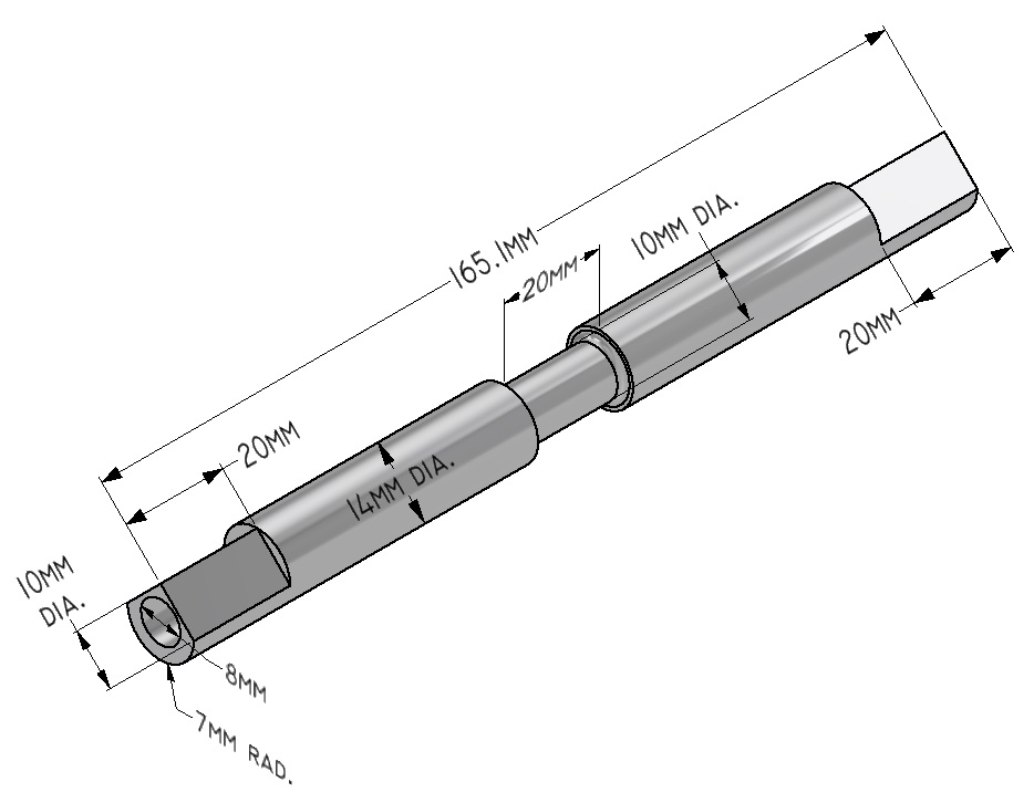
Fig. 6.11 Torsion Specimen - SMT001.
Gleeble’s Torsion MCU specimens are designed specifically to provide optimal results for a torsion test. The Torsion MCU is capable of accepting a wide variety of specimen geometries. However, specimens designed according to DSI’s recommendations will perform better.
Specimen geometry will vary with the specific test being performed. DSI has identified recommended specimen geometries for commonly performed simulation tests. Contact Dynamic Systems for assistance identifying a recommended specimen geometry.
| Popular Specimen Sizes | ||||
|---|---|---|---|---|
| Specimen Length | Gauge Diameter | Gauge Length | Collet Size | Drawing Number |
| 165.1 mm | 10 mm | 20 mm | 14 mm | SMT001 |
| 165.1 mm | 10 mm | 14.4 mm | 10 mm | SMT007 |
| 165.1 mm | 5.7 mm | 11.4 mm | 8 mm | SMT008 |
6.3.4. Collet Grips
The Hot Torsion MCU retains specially designed samples through the use of Stainless Steel collet grips. Redesigned in 2020, the Mark II Collet Grips are backward compatible for all Torsion MCUs. The redesigned grips make use of a single installation and removal tool, enabling researchers to quickly and easily change from one specimen size to another. The collet grip redesign also introduced a single top clamp designed for all thermal profiles. These redesigns further simplify the installation and testing of a torsion specimen.
Each Collet Grip Kit includes two clamps, two bases, and all necessary hardware to secure and orient the collet grips.
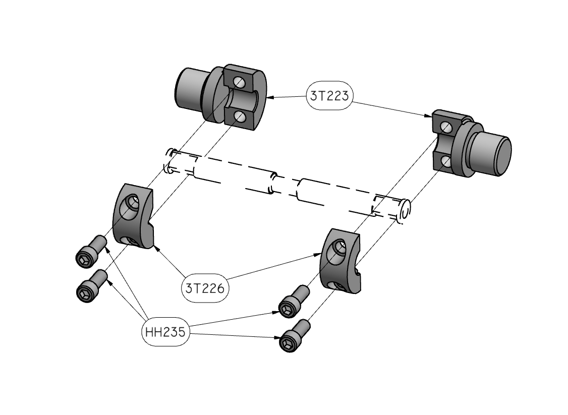
Fig. 6.12 3T941 14 mm Collet Grips.
| Part Number | Description | Sold As |
|---|---|---|
| 8 mm Collet Grips | ||
| 3T943 | 8 mm Collet Grip | Kit |
| 3T228 | Jaw Clamp - Top | Ea. |
| 3T225 | Jaw Base - Bottom | Ea. |
| 10 mm Collet Grips | ||
| 3T942 | 10 mm Collet Grip | Kit |
| 3T227 | Jaw Clamp - Top | Ea. |
| 3T224 | Jaw Base - Bottom | Ea. |
| 14 mm Collet Grips | ||
| 3T941 | 14 mm Collet Grip | Kit |
| 3T226 | Jaw Clamp - Top | Ea. |
| 3T223 | Jaw Base - Bottom | Ea. |
| All Collet Grips | ||
| 3T821 | Collet Grip Installation Tool | Ea. |
| 3T143 | 0.020 in Copper Washer | Ea. |
| 3T144 | 0.040 in Copper Washer | Ea. |
| 3T188 | 0.015 in Copper Washer | Ea. |
| HH235 | 5/16 - 18 x 3/4 in Bolt | Ea. |
6.3.5. Replacement Parts
| Part Number | Description | Sold As |
|---|---|---|
| 3T948 | Torsion Upgrade to enable heating during rotation. Slip Ring Drive Side Ground Assembly including Torsion Test Samples | Ea. |
| 3T086 | Shear Pin | Ea. |
| 3T958 | Torsion Grip Set Assembly - Through- Specimen Gas Cooling | Kit |
| 3T947 | Torsion Slip Ring Drive-Side Ground Assembly | Kit |
| 3T939 | Torsion End Heater Mounting Block with Face Seal - Mark II Design | Kit |
| 3T131-L | Mounting Gauge Spacer Clip – Left Hand Side | Ea. |
| 3T131-R | Mounting Gauge Spacer Clip – Right Hand Side | Ea. |
| 3T126 | Strip Heater - 2 heaters per set | Set |
6.3.6. MCU Dimensions
| Equipment | Height | Depth | Width | Weight |
|---|---|---|---|---|
| Hot Torsion MCU | 158 cm (62 in) | 84 cm (33 in) | 150 cm (59 in) | 683.1 kg (1,506 lb) |
6.4. MAXStrain II
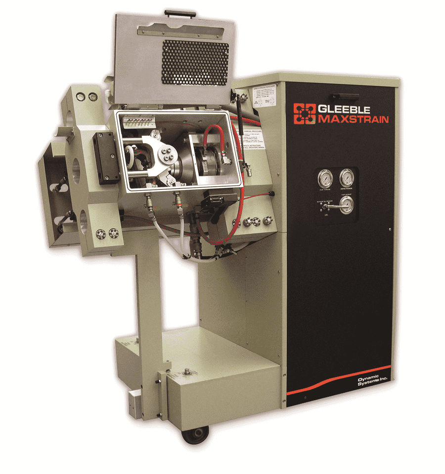
Fig. 6.13 MAXStrain II MCU - DSI# 35038.
The MAXStrain II multi-axis hot deformation system is a unique research tool that can subject materials to virtually unlimited strain under precise control of strain, strain rate, and temperature.
Specimens loaded into the MAXStrain are heated and rotated 90 degrees between multiple, successive compressions. The system restrains specimens lengthwise while allowing unlimited deformation in the other two dimensions. As a result, very high strain levels can be introduced into specimens to produce a sample of ultrafine grain or nano-scale material that is large enough for subsequent materials properties testing.
The MAXStrain provides an unparalleled degree of accuracy and reproducibility. Researchers can quickly and precisely produce target grain structure refinements in a laboratory environment. For anvil assemblies and consumables, see Plane Strain Studies.
| Part Number | Description | Sold As |
|---|---|---|
| 35038 | MAXStrain II MCU for Gleeble 3800 | Ea. |
Note
The MAXStrain II MCU is only compatible with the Gleeble 3800-GTC.
6.4.1. Hydro-Mechanical
| Characteristic | Specification |
|---|---|
| Test Frame | Horizontal type with dual 99 mm (3.9 inches) dia columns |
| Mechanical System | Closed-loop hydraulic servo control |
| Maximum Static Force in Compression | 20,000 kg (~44,000 lb) (196 kN) |
| Maximum Dynamic Force in Compression | 8,000 kg (~ 7,600 lb) (80 kN) at 700 mm/s (27.5 in/s) |
| Maximum Stroke Rate in Compression | 350 mm/s (13.7 in/s) |
| Minimum Stroke Rate in Compression | 0.01 mm/s (3.936996-4 in/s) |
| Maximum Stroke Distance | 36 mm (1.41 in) |
| Maximum Number of Compression Hits | No Specific Limit |
Note
Accuracy is measured at a temperature of 23°C (73°F). Maximum stroke rates are at a hydraulic pressure of 203 bar (2,950 psi) ±3 % and an oil temperature of 30°C (86°F).
6.4.1.1. Load Cell
| Characteristic | Specification |
|---|---|
| Non-linearity | ±0.1 % of full scale |
| Hysteresis | ±0.08 % of full scale |
| Non-Repeatability (Maximum) | ±0.03 % of full scale |
| Overload Rating | 150 % of capacity |
| Deflection - Full Scale | 0.076 mm (0.003 in) |
| Force Measurement Accuracy | ±1.0 % of full scale |
| Force Measurement Resolution | ±1 kgf (2.2 lbf) |
Note
Accuracy is measured at a temperature of 23°C (73°F). Maximum stroke rates are at a hydraulic pressure of 203 bar (2,950 psi) ±3 % and an oil temperature of 30°C (86°F).
6.4.1.2. MAXStrain II - Stroke Transducer
| Characteristic | Specification |
|---|---|
| Type | LVDT |
| Linear Range | ±25.4 mm (±1.0 in) |
| Linearity | ±0.25 % of full scale |
| Stroke Measurement Accuracy | ±0.5 % of full scale |
| Stroke Measurement Resolution | 0.002 mm (7.87-5 in) |
Note
Accuracy is measured at a temperature of 23°C (73°F). Maximum stroke rates are at a hydraulic pressure of 203 bar (2,950 psi) ±3 % and an oil temperature of 30°C (86°F).
6.4.2. Thermal Subsystem
The MAXStrain II MCU heats a specimen with direct resistance heating.
Direct resistance heating provides the ability to reproduce the wide variety of thermal profiles that materials undergo in actual processes. This is critical to the success of thermal-mechanical testing and physical simulation. All Gleeble systems have high-speed heating and cooling rates that can accurately replicate nearly any thermal profile required.
| Characteristic | Specification |
|---|---|
| Heating System Type and Control | Direct resistance with closed-loop control |
| Temperature Range | Room Temperature to 1,700°C (3,092°F) |
| Thermocouple Sampling Rate | Twice the power line frequency (100 - 120 Hz) |
| Resolution | ±1°C or°F |
| Maximum number of Thermal Channels | 4 thermocouple channels, or 2 thermocouple channels and 1 pyrometer channel |
| Accuracy of Control | ±1°C (in steady state) |
| Accuracy of Measurement | ±2°C or ±1 % of temperature (whichever is greater) plus the accuracy of the thermocouple wire (in steady state) |
Note
As the specimen size, diameter, length, or cross-sectional area increases the effective heating rate will decrease.
6.4.2.1. Heating Rates
The maximum heating rates listed below are average rates for 1018 carbon steel specimen using a 480 V / 200 A power supply and standard MAXStrain II grips and resistance heating.
| Specimen | Free Span | Drawing Number | Maximum Heating Rate |
|---|---|---|---|
| °C/s (°F/s) | |||
| 15 mm Sq x 195.58 mm long with reduced center | 10 mm square x 12 mm long | SMC408B | 50 (90) |
6.4.3. Cooling Rates
6.4.3.1. Free Cooling Rates
The Gleeble system is able to control the specimen cooling rate based on conductive heat transfer. The efficiency and maximum rate of conductive cooling is directly impacted by grip and specimen geometry, material, cleanliness, and system’s chilled process fluid flow rate.
The following cooling rates are average rates for 1018 carbon steel specimen (SMC408B) using standard MAXStrain grips and conductive cooling.
| Specimen | Drawing Number | Temperature Range | Cooling Rate |
|---|---|---|---|
| °C (°F) | °C/s (°F/s) | ||
| 15 mm Sq x 195.58 mm long | SMC408B | 1,000-800 (1,832-1,472) | 15 (27) |
| 800-500 (1,472-932) | 7 (12.6) | ||
6.4.3.2. Quench Cooling Rates
Optional quench systems are available which can use compressed air or inert gas to cool the specimen at high rates. A mixture of compressed air and water can also be used as a quench medium for even higher cooling rates.
The maximum cooling rates listed below are average rates for 1018 carbon steel specimens, water quenched, using a 59013 High Flow Quench system. See Quench Systems for more information about quench kits and quench tanks.
| Specimen | Drawing Number | Temperature Range | Cooling Rate |
|---|---|---|---|
| °C (°F) | °C/s (°F/s) | ||
| 15 mm Sq x 191.77 mm long | SMC408B | 1,000-500 (1,832-932) | 550 (990) |
| 15 mm Sq x 191.77 mm long with ISO-Q Quench | SMC409B | 1,000-500 (1,832-932) | 50 (90) |
6.4.4. Temperature Uniformity Within the Specimen
The Gleeble system has the unique ability to control the temperature uniformity and thus the thermal gradient within the test specimen. Tests can either be performed with very uniform thermal gradient within the specimen’s work zone cross-sectional area, or with the large thermal gradients needed to accurately simulate welding and other processes.
Thermal gradients within a specimen are dependent upon:
|
|
The following specimen data were obtained using standard Stainless Steel MAXStrain II contact grips. Measurements were taken at steady state temperatures.
| Specimen | Free Span | Drawing Number | Temperature Uniformity |
|---|---|---|---|
| 15 mm Sq x 172.7 mm long | 10 mm x 12 mm reduced | SMC409B | ±3 % of Tavg for 10 mm of midspan |
Note
Tavg is the average of the specimen cross sectional temperature at 1,000°C (1,832°F).
6.4.5. Specimen Size Considerations
Gleeble systems are capable of testing a wide variety of material compositions and specimen geometries. Inherent limitations of the system, such as distance between the jaw or anvil faces, the maximum or minimum stroke speed, test temperature, and force limitations for the individual system must be considered when selecting a specific specimen geometry.
The target temperature of a test will also impact the size of a specimen that can safely be tested with a Gleeble system. For example, when considering a standard uniaxial compression specimen, it is possible for a soft material such as aluminum or copper to be tested at ambient temperature. Harder materials, such as steel or titanium alloys, are expected to be tested at elevated temperatures.
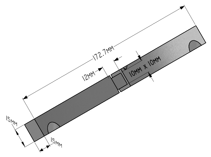
Fig. 6.14 MaxStrain Specimen - SMC408.
The MAXStrain II’s vacuum tank configuration limits the maximum and minimum sample geometry that can be tested.
Specimen geometry will vary with the specific test being performed. DSI has identified recommended specimen geometries for commonly performed simulation tests. Contact Dynamic Systems for assistance identifying a recommended specimen geometry.
| Popular Specimen Sizes | ||||
|---|---|---|---|---|
| Specimen Length | Specimen Size | Gauge Size | Gauge Length | Drawing Number |
| 195.58 mm | 15 mm Sq | 10 mm Sq | 12 mm | SMC408 |
| 191.77 mm | 15 mm Sq | 10 mm Sq | 12 mm | SMC409 |
| 195.58 mm | 15 mm Sq | 15 mm Sq | 12 mm | SMC416 |
6.4.6. MCU Dimensions
| Equipment | Height | Depth | Width | Weight |
|---|---|---|---|---|
| MAXStrain II MCU | 158 cm (62 in) | 84 cm (33 in) | 150 cm (59 in) | 953.9 kg (2,103 lb) |
6.5. Large-Sample Strip Annealing
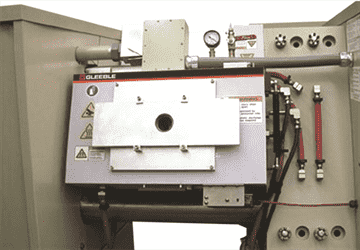
Fig. 6.15 Large-Sample Strip Annealing MCU - DSI# 35025.
The Large-Sample Strip Annealing Mobile Conversion Unit (MCU) is designed to provide controlled heating and cooling cycles on large sheet steel specimens for replicating the heating and cooling cycles of sheet annealing processes.
The test specimen size is large enough to allow subsequent mechanical testing of the material, including furnishing limiting dome height test and tensile test coupons.
This MCU’s capabilities offer valuable tools to researchers and production engineers as they set up new continuous strip annealing lines, optimize existing lines, or efficiently develop new products and processes.
This MCU is equipped with the following:
- Vacuum tank for atmosphere control
- Spray heads and valve controls for air/gas quenching of specimens
- Quench valve controls integrated with the Gleeble computer
- Safety interlocks on the vacuum door for heat and mechanical operation
- Pneumatic grips for easy loading/unloading and consistent clamping pressures
| Part Number | Description | Sold As |
|---|---|---|
| 35025 | Large-Sample Strip Annealing MCU | Ea. |
6.5.1. Thermal Subsystem
The Large-Sample Strip Annealing MCU heats a specimen with direct resistance heating.
Direct resistance heating provides the ability to reproduce the wide variety of thermal profiles that materials undergo in actual processes. This is critical to the success of thermal-mechanical testing and physical simulation. All Gleeble systems have high-speed heating and cooling rates that can accurately replicate nearly any thermal profile required.
| Characteristic | Specification |
|---|---|
| Heating System Type and Control | Direct resistance with closed-loop control |
| Temperature Range | Room temperature to 900°C (1,652°F) |
| Maximum Heating Rate | 15°C/s (27°F) |
| Thermocouple Sampling Rate | Twice the power line frequency (100 - 120 Hz) |
| Resolution | ±1°C or°F |
| Maximum Number of Thermal Channels | 4 thermocouple channels, or 2 thermocouple channels and 1 pyrometer channel |
| Accuracy of Control | ±1°C (in steady state) |
| Accuracy of Measurement | ±2°C or ±1 % of temperature (whichever is greater) plus the accuracy of the thermocouple wire (in steady state) |
Note
As the specimen size, diameter, length, or cross-sectional area increases the effective heating rate will decrease.
6.5.1.1. Thermal Gradient Considerations
For Gleeble systems with a standard 75 kVA heating transformer, standard specimen length is 254 mm (10 in). The chart below indicates maximum width based on specimen thickness. The temperature uniformity data is valid from 250 - 900°C (482 - 1,652°F). Thermal uniformity within a specimen is reported as the difference between the temperature measurement at the center and the temperature measurement at the edge of the specimen. Each specimen’s thermocouples are configured in the same manner. Three thermocouples are placed in specific locations on the specimen to verify the average temperature of the desired thermal uniformity area. The average temperature uniformity zone during the heating, holding and cooling cycles are listed based on the specimen size.
| Specimen Thickness | Specimen Width | Uniform Zone Width | Uniform Zone Length | Temperature Uniformity on Heating | Temperature Uniformity on Holding | Temperature Uniformity on Cooling |
|---|---|---|---|---|---|---|
| °C (°F) | °C (°F) | °C (°F) | ||||
| 1 mm | 127 mm | 76 mm | 76 mm | ±15 (59) | ±15 (59) | ±25 (77) |
| 2 mm | 127 mm | 76 mm | 76 mm | ±15 (59) | ±20 (68) | ±25 (77) |
| 3 mm | 127 mm | 76 mm | 76 mm | ±20 (68) | ±20 (68) | ±20 (68) |
Thermal uniformity within the specimen is verified by measuring thermocouples secured onto the specimen. The TC positioning measurements below use the top of the left edge of the specimen as an origin point. Secure thermocouples at the following location.
- TC1 Center: 127 mm x 63.5 mm (4.99 in x 2.49 in)
- TC2 38 mm above TC1: 165 mm x 63.5 mm (6.49 in x 2.49 in)
- TC3 38 mm to the right of TC1: 127 mm x 101.5 mm (6.49 in x 3.99 in)
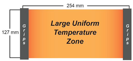
Fig. 6.16 Thermocouple Placement.
6.5.1.2. Heating Rate
Heating rates are based on using a 480 V / 200 A power supply, standard Large-Sample Strip Annealing grips, and 1018 carbon steel specimens in the Large-Sample Strip Annealing MCU.
| Specimen | Thickness | Drawing Number | Maximum Heating Rate |
|---|---|---|---|
| °C (°F) | |||
| 254 mm long x 127 mm wide | 1 mm | SMF114B | 15 (59) |
| 254 mm long x 127 mm wide | 2 mm | SMF115B | 15 (59) |
| 254 mm long x 127 mm wide | 3 mm | SMF116B | 15 (59) |
6.5.1.3. Cooling Rate
The Gleeble system is able to control the specimen cooling rate based on conductive heat transfer. The efficiency and maximum rate of conductive cooling is directly impacted by grip and specimen geometry, material, cleanliness, and system’s chilled process fluid flow rate.
Cooling rates are achieved using standard Large-Sample Strip Annealing grips, and 1018 carbon steel specimens in the Large-Sample Strip Annealing MCU, a Proportional Quench System valve; and compressed nitrogen (N2) gas.
| Specimen | Specimen Thickness | Drawing Number | Temperature Range | Cooling Rate |
|---|---|---|---|---|
| °C (°F) | °C/s (°F/s) | |||
| 254 mm long x 127 mm wide | 1 mm | SMF114B | 900-500 (1,1652-932) | 20 (36) |
| 254 mm long x 127 mm wide | 2 mm | SMF115B | 900-500 (1,1652-932) | 17.5 (31.5) |
| 254 mm long x 127 mm wide | 3 mm | SMF116B | 900-500 (1,1652-932) | 17.5 (31.5) |
6.5.2. Specimen Size Considerations
Gleeble systems are capable of testing a wide variety of material compositions and specimen geometries. Inherent limitations of the system, such as distance between the jaw or anvil faces, the maximum or minimum stroke speed, test temperature, and force limitations for the individual system must be considered when selecting a specific specimen geometry.
The target temperature of a test will also impact the size of a specimen that can safely be tested with a Gleeble system. For example, when considering a standard uniaxial compression specimen, it is possible for a soft material such as aluminum or copper to be tested at ambient temperature. Harder materials, such as steel or titanium alloys, are expected to be tested at elevated temperatures.
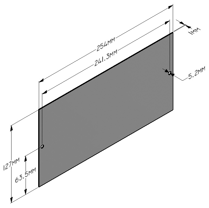
Fig. 6.17 Large-Sample Strip Annealing Specimen - SMF114.
The Large-Sample Strip Annealing MCU’s vacuum tank configuration limits the maximum and minimum sample geometry that can be tested.
Specimen geometry will vary with the specific test being performed. DSI has identified recommended specimen geometries for commonly performed simulation tests. Contact Dynamic Systems for assistance identifying a recommended specimen geometry as needed.
| Popular Specimen Sizes | |||
|---|---|---|---|
| Thickness | Length | Width | Drawing Number |
| 1 mm | 254 mm | 127 mm | SMF114 |
| 2 mm | 254 mm | 127 mm | SMF115 |
| 3 mm | 254 mm | 127 mm | SMF116 |
| 4 mm | 254 mm | 127 mm | SMF117 |
6.5.3. Pneumatic
The Large-Sample Strip Annealing MCU is equipped with a pneumatic system to actuate the specimen retention grips. The pneumatic system also applies a minimal tensile force on the specimen to prevent buckling during a test.
6.5.4. MCU Dimensions
| Equipment | Height | Depth | Width | Weight |
|---|---|---|---|---|
| Strip Annealing MCU | 158 cm (62 in) | 86 cm (34 in) | 157 cm (62 in) | 565 kg (1,245 lb) |
6.6. High-Temperature MCU
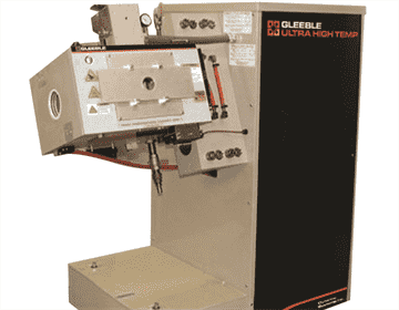
Fig. 6.18 High-Temperature General-Purpose MCU - DSI# 35024.
The High-Temperature MCU is used for testing or simulation applications that require high-temperatures for extended periods of time. The High-Temperature General-Purpose Mobile Conversion Unit (MCU) offers enhanced capabilities to accommodate more demanding requirements. This MCU is based on the General-Purpose Mobile Conversion Unit MCU, which allows for the use of standard specimen grips and accessories.
The High-Temperature General-Purpose MCU is available for both the Gleeble 3500-GTC and the Gleeble 3800-GTC systems.
| Characteristic | Specification |
|---|---|
| Heating System Type and Control | Direct resistance with closed-loop control |
| Temperature Range | -150 to 3,000°C (-238 to 5,432°F) |
| Temperature Monitoring Source | Thermocouple or Optional Pyrometer Control Cameras |
| Thermocouple Sampling Rate | Twice the power line frequency (100 - 120 Hz) |
| Resolution | ±1°C or°F |
| Maximum Number Of Simultaneous Thermal Channels | 4 thermocouple channels, or 2 thermocouple channels and 1 pyrometer channel |
| Accuracy of Control | ±1°C (in steady state) |
| Accuracy of Measurement | ±2°C or ±1 % of temperature (whichever is greater) plus the accuracy of the thermocouple wire (in steady state) |
Note
An optional Pyrometer Control Camera is required for temperatures above 2,100°C (3,812°F). An optional Cryogenic Quench System kit is required for temperatures below room temperature.
Note
As the specimen size, diameter, length, or cross-sectional area increases the effective heating rate will decrease.
| Part Number | Description | Sold As |
| 35023 | High-Temperature Testing MCU for Gleeble 3500C | Ea. |
| 35024 | High-Temperature Testing MCU for Gleeble 3800 | Ea. |
6.6.1. MCU Dimensions
| Equipment | Height | Depth | Width | Weight |
|---|---|---|---|---|
| General-Purpose MCU for 3500C and 3800 | 158 cm (62 in) | 86 cm (34 in) | 157 cm (62 in) | 565 kg (1,245 lb) |
6.7. MCU Superbolts
Standard Mobile Conversion Units, MCUs, are secured to the Gleeble Load Unit with Superbolts. Secured with DSI-supplied hand tools, the Superbolts apply adequate clamping force to secure each MCU for high-speed, high strength testing.
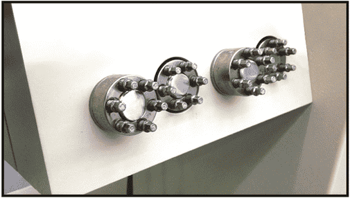
Fig. 6.19 Superbolt Assembly.
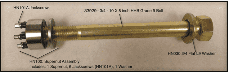
Fig. 6.20 Parts of a Superbolt Assembly.
| Part Number | Description | Sold As |
|---|---|---|
| 33929 | Supernut Bolt | Ea. |
| HN100 | Supernut with Washer | Ea. |
| HN101A | Jack Bolt for MCU Superbolts | Ea. |
| HN030 | 3/4 in Supernut Washer | Ea. |
| G389X | 3/16 in Impact Socket, 1/4 in Drive for HN101A | Ea. |
| HN101B | Superbolt Lubricant | Ea. |
| HN103A | Torquing Screw for Load Cell Superbolts | Ea. |
6.8. Hydraulic Crosshead Locks
DSI has introduced a new hydraulic crosshead locking system that eliminates the need for Superbolts and jack screws while maintaining optimal performance and system stiffness. These hydraulic locks greatly reduce the time required to switch MCUs, allowing Gleeble users to be more productive and spend more time running tests, and less time configuring equipment.
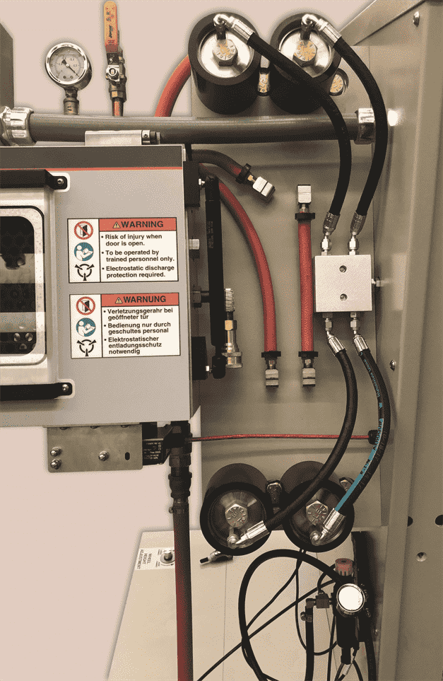
Fig. 6.21 Hydraulic Cross Head Locks.
Crosshead locks automatically engage when the Gleeble is powered on, ensuring a secure connection between the MCU and the Gleeble load unit. The hydraulic lock set include multiple locks, which are powered by an independent hydraulic system. The independent hydraulic pump is installed inside the Gleeble Load Unit. The second hydraulic pump ensures the Gleeble system continues to operate with the full potential power of it’s standard hydraulic system; the same as systems not equipped with Hydraulic Cross Head Locks.
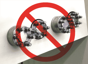
Fig. 6.22 Hydraulic Crosshead Locks Eliminate the Need for Superbolts.
The Hydraulic Crosshead Locking System is not a standard feature. It is available as an option on new Gleeble systems and as a retrofit for most existing Gleeble MCUs. The system requires installation by a Certified Systems Service Engineer. The Hydraulic Power Pack is permanently incorporated into the Load Unit with dedicated locks installed on each MCU. Hydraulic quick-connect fittings allow for easy MCU hook-up to the load unit. Each MCU requires a different number of hydraulic locks. For instance, a Gleeble 3800 General-Purpose MCU utilizes 8 hydraulic locks.
6.8.1. Hydraulic Power Pack
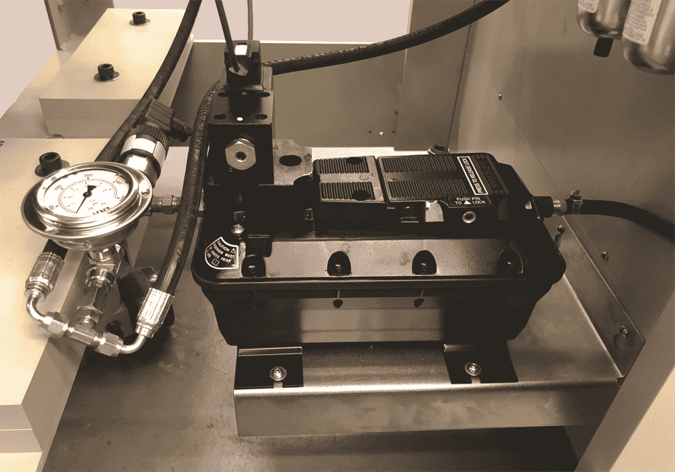
Fig. 6.23 Hydraulic Power Pack for Hydraulic Crosshead Locks.
The hydraulic power pack used with hydraulic crosshead locks is installed in the Gleeble Load Unit. With a pneumatic supply pressure of 5.51 bar (80 psi) a single hydraulic power pack supports all of the hydraulic crosshead locks installed on the MCUs.
| Part Number | Description | Sold As |
|---|---|---|
| 37620 | Power Pack For Hydraulic Crosshead Locks - Factory Installed | Ea. |
| 37620-GR | Power Pack For Hydraulic Crosshead Locks - Retrofit for GTC Console | Ea. |
| 37620-3R | Power Pack For Hydraulic Crosshead Locks - Retrofit for Series 3 Control Console | Ea. |
6.8.2. Gleeble 3500C Crosshead Locks
Each Hydraulic Crosshead Locks kit contains all of the required parts to be installed on a single, designated MCU. To fully retrofit or configure multiple MCUs, multiple Hydraulic Crosshead Locks kits are required.
The Hydraulic Crosshead Locks for a High-Temperature General-Purpose MCU utilize the same parts as the Hydraulic Crosshead Locks for a General-Purpose MCU. The Large-Sample Strip Annealing MCU can be retrofitted with the Torsion MCU’s Hydraulic Crosshead Locks kit.
| Crosshead Locks for Gleeble 3500C | |
|---|---|
| General-Purpose or High-Temperature General-Purpose MCU - 4 Locks per MCU | |
| 37601 | Factory Installed |
| 37601-GR | Retrofit for GTC |
| 37601-3R | Retrofit for Series 3 Control Console |
| Hydrawedge II MCU - 8 Locks per MCU | |
| 37606 | Factory Installed |
| 37606-GR | Retrofit for GTC |
| 37606-3R | Retrofit for Series 3 Control Console |
| Torsion or Large-Sample Strip Annealing MCU - 4 Locks per MCU | |
| 37610 | Factory Installed |
| 37610-GR | Retrofit for GTC |
| 37610-3R | Retrofit for Series 3 Control Console |
6.8.3. Gleeble 3800 Crosshead Locks
Each Hydraulic Crosshead Locks kit contains all of the required parts to be installed on a single, designated MCU. To fully retrofit or configure multiple MCUs, multiple Hydraulic Crosshead Locks kits are required.
The Hydraulic Crosshead Locks for a High-Temperature General-Purpose MCU utilize the same parts as the Hydraulic Crosshead Locks for a General-Purpose MCU. The Large-Sample Strip Annealing MCU can be retrofitted with the Torsion MCU’s Hydraulic Crosshead Locks kit.
| Crosshead Locks for Gleeble 3800 | |
|---|---|
| General-Purpose or High-Temperature General-Purpose MCU - 8 Locks per MCU | |
| 37600 | Factory Installed |
| 37600-GR | Retrofit for GTC |
| 37600-3R | Retrofit for Series 3 Control Console |
| Hydrawedge II MCU - 14 Locks per MCU | |
| 37605 | Factory Installed |
| 37605-GR | Retrofit for GTC |
| 37605-3R | Retrofit for 3000 Series |
| MAXStrain MCU - 10 Locks per MCU | |
| 37615 | Factory Installed |
| 37615-GR | Retrofit for GTC |
| 37615-3R | Retrofit for Series 3 Control Console |
| Torsion or Large-Sample Strip Annealing MCU - 4 Locks per MCU | |
| 37610 | Factory Installed |
| 37610-GR | Retrofit for GTC |
| 37610-3R | Retrofit for Series 3 Control Console |