15. Plane Strain Studies
15.1. Plane Strain Compression Testing
In plane strain compression testing, a plate-shaped specimen is subjected to primary compression in the thickness (h) direction, which subsequently results in positive strain deformation of the plate normal to the width of the plate (w direction). In order to minimize the amount of material spread in the length direction of the specimen (t), it is necessary that t > w. When the spread in the length direction is minimized, plane strain conditions are achieved. When relatively large values of the ratio of the plate breadth to the specimen thickness (w > h) are studied, essentially homogeneous deformation occurs between the plates. When the w:h ratio is small, a greater amount of non-homogeneous deformation occurs. During plane strain compression, the w : h ratio will increase and may cause a transition from homogeneous deformation to heterogeneous deformation.
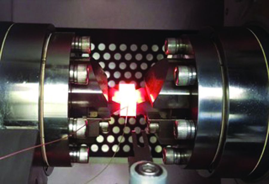
Fig. 15.1 Plane Strain Compression Test.
Because of the stress and strain conditions found in plane strain compression test, higher anvil pressure values, and lower strain values are theoretically recorded when compared to stress/strain values measured in the uniaxial compression tests.
When the direct resistance heating current is applied to the specimen, bulk heating, and hence nominally uniform temperatures, are noted in the volume of material between the anvil contact surfaces. The edge material outside of the anvil faces is not heated by the heating current to the same extent as the material between the anvils. This heating method provides for heating of the entire specimen over a relatively short period of time. However, uniform temperatures are not always preferred. Cooler ends help to constrain the material from deformation in the “t” direction. The cooler ends act as heat sinks. This simulates a rolling mill’s inter-pass cooling profiles, between or during deformation steps.
Plane strain compression testing is primarily used to study and simulate the types of stress states and flow patterns associated with rolling mill metal working conditions. However, plane strain compression testing can also be useful when conducting other complex simulations in which plane strain conditions are expected.
Conducting Tests Using Gleeble’s Plane Strain Testing Assemblies
To prevent barreling of the specimen, the application of suitable Diffusion Barriers at the interface between the anvils and the specimen is recommended. The diffusion barrier prevents diffusion bonding. This creates near frictionless contact between the specimen and the anvils. Allowing the specimen free movement against the anvils.
Hot Deformation Software (HDS) can be used to perform a plane strain compression test in conjunction with a Hydrawedge II.
15.2. Plane Strain Anvil Assemblies
Gleeble systems use unique anvil assemblies to conduct Plane Strain simulations. The anvil assemblies are designed to fit seamlessly into the jaws of the General-Purpose MCU, or bolt directly to the moving shafts of the Hydrawedge of MaxStrain MCUs.
15.2.1. Small Plane Strain
Small Plane Strain Anvil Assemblies use 5 x 25 x 10 mm (0.196 x 0.984 x 0.393 in) anvils.
General-Purpose MCU - Pocket Jaw Mounted
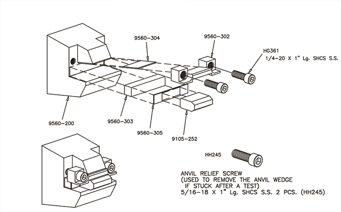
Fig. 15.2 Pocket Jaw Mounted - Small Plane Strain Assembly - DSI# 9560-001.
| Part Number | Description | Sold As |
|---|---|---|
| 9560-001 | Small Plane Strain Jaw System Assembly - General-Purpose MCU | Kit |
| 9560-003 | Small Plane Strain Jaw System - 3180 | Kit |
| 9560-200 | Pocket Jaw Wedge Mount - Small Plane Strain | Ea. |
| Parts Used With Pocket Jaw, 563, Hydrawedge II, and Compression Tester Adapter Assemblies | ||
| 9560-304 | Side Conductor Plate - Small Plane Strain | Ea. |
| 9560-305 | Bottom Conductor Plate - Small Plane Strain | Ea. |
| 9560-302 | Wedge Block - Small Plane Strain | Ea. |
| 9560-303 | Backing Block - Small Plane Strain | Pack of 2 |
| HH245 | Anvil Relief Screw - Small Plane Strain | Ea. |
| HG361 | Wedge Block Retention Screw - Small Plane Strain - 1/4-20 x 1.00 Stainless Steel | Ea. |
| 9555-516 | 4 mm High-Temperature Mica Sheet - 24 x 39 in | Sheet |
Hydrawedge II or Compression Tester Adapter Mounted
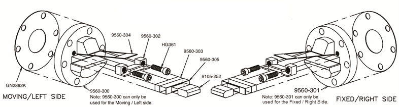
Fig. 15.3 Hydrawedge II Mounted - Small Plane Strain Anvil Assembly - DSI# 9560-100.
| Part Number | Description | Sold As |
|---|---|---|
| 9560-100 | Small Plane Strain Anvil Assembly - Hydrawedge II | Kit |
| 9560-103 | Small Plane Strain Anvil Assembly - Compression Test Adapter | Kit |
| 9560-300 | Left Side Anvil Base - Small Plane Strain | Ea. |
| 9560-301 | Right Side Anvil Base - Small Plane Strain | Ea. |
| GN2882K | Copper Backup Plate - Hydrawedge II and Compression Test Adapter Set | Ea. |
| GN2876GA | Plane Strain Anvil Mount - Small Plane Strain - Mounts Anvil Assembly to Moving Shafts | Ea. |
563 Pocket Jaw
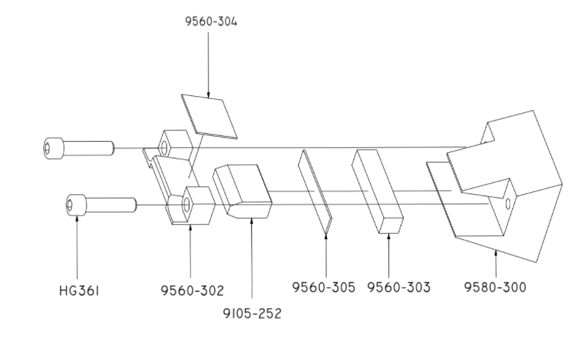
Fig. 15.4 563 Mounted - Small Plane Strain Anvil Assembly - DSI# 9580-100.
| Part Number | Description | Sold As |
|---|---|---|
| 9580-100 | Small Plane Strain Anvil Assembly - 563 | Kit |
| 9580-300 | Pocket Jaw Wedge Mount - Small Plane Strain - 563 | Ea. |
15.2.2. Large Plane Strain
Large Plane Strain Anvil Assemblies use 10 x 42 x 20 mm (0.393 x 1.653 x 0.787 in) anvils.
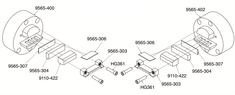
Fig. 15.5 Hydrawedge II Mounted - Large Plane Strain Anvil Assembly - DSI# 9565-107.
| Part Number | Description | Sold As |
|---|---|---|
| 9565-107 | Large Plane Strain Anvil Assembly - Hydrawedge II | Kit |
| 9565-108 | Large Plane Strain Anvil Assembly - Compression Test Adapter | Kit |
| 9565-303 | Wedge Block - Large Plane Strain | Ea. |
| 9565-304 | Backing Block - Large Plane Strain | Ea. |
| 9565-306 | Side Conductor Plate - Large Plane Strain | Ea. |
| 9565-307 | Bottom Conductor Plate - Large Plane Strain | Ea. |
| GN2876LA | Copper Conducting Disk - Large Plane Strain | Ea. |
| 9565-400 | Left Side Anvil Base - Large Plane Strain - Water-Cooled | Ea. |
| 9565-402 | Right Side Anvil Base - Large Plane Strain - Water-Cooled | Ea. |
15.2.3. MAXStrain
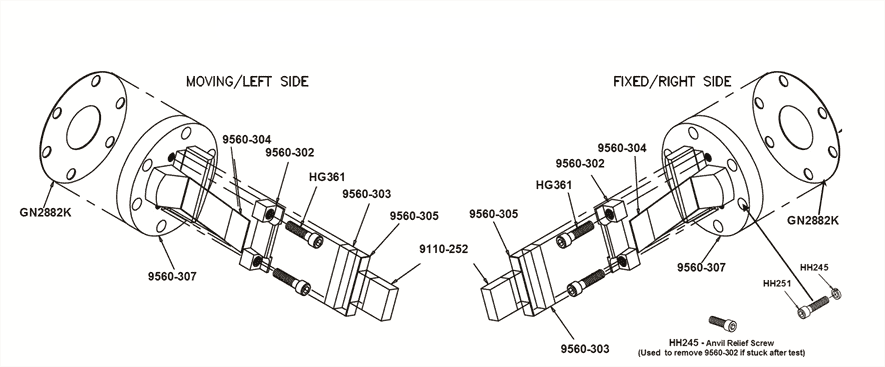
Fig. 15.6 MAXStrain II Mounted -Plane Strain Anvil Assembly - DSI# 9560-108.
| Part Number | Description | Sold As |
|---|---|---|
| 9560-108 | Plane Strain Anvil Assembly - MAXStrain 10 x 25 x 10 mm (0.393 x 0.984 x 0.393 in) | Kit |
| 9560-307 | Plane Strain Base - MAXStrain | Ea. |
| 9560-304 | Side Conductor Plate - MAXStrain | Ea. |
| 9560-302 | Wedge Block - MAXStrain | Ea. |
| 9560-303 | Bottom Conductor Plate -MAXStrain | Ea. |
| 9560-305 | Backing Block - MAXStrain | Ea. |
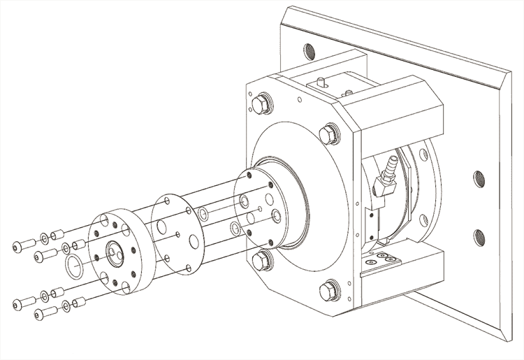
Fig. 15.7 MAXStrain Anvil Bases - DSI# 3M954.
| Part Number | Description | Sold As |
|---|---|---|
| 3M954 | Anvil Bases - MAXStrain | Kit |
| 3M263 | Insulating Disk - Anvil Base to Moving Shaft - MAXStrain | Ea. |
| 3M303 | Insulating Washer - MAXStrain | Ea. |
| 3M304 | Insulating Bushing - MAXStrain | Ea. |
| 9560-307 | Plane Strain Base - MAXStrain | Ea. |
| ORS112 | O-Ring | Ea. |
15.3. Plane Strain Anvils
Plane strain tests are frequently used in the simulation of rolling. Fig. 15.8 shows the basis for this, where the deformation forces, strain and heat flow are all in the same direction as those found in rolling.
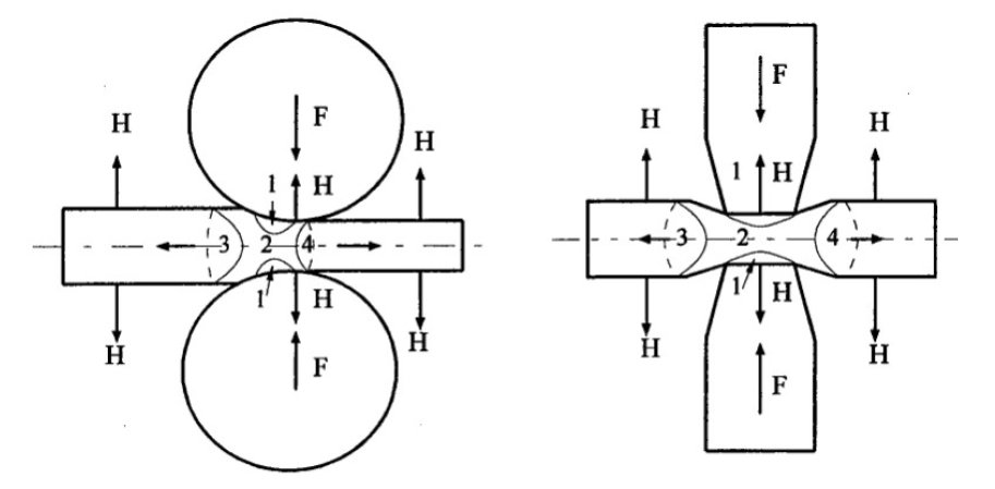
Fig. 15.8 Hot Rolling Process Simulation.
Recommended Maximum Operating Temperatures for Compression Anvils Tungsten Carbide 1,200°C (2,192°F ) Pure Tungsten 1,400°C (2,552°F ) Tungsten Composite 1,700°C (3,092°F ) Quartz
Silicon Nitride
15.3.1. Small Plane Strain
Small Plane Strain Anvil Assemblies use 5 x 25 x 20 mm (0.196 x 0.984 x 0.787 in) anvils.
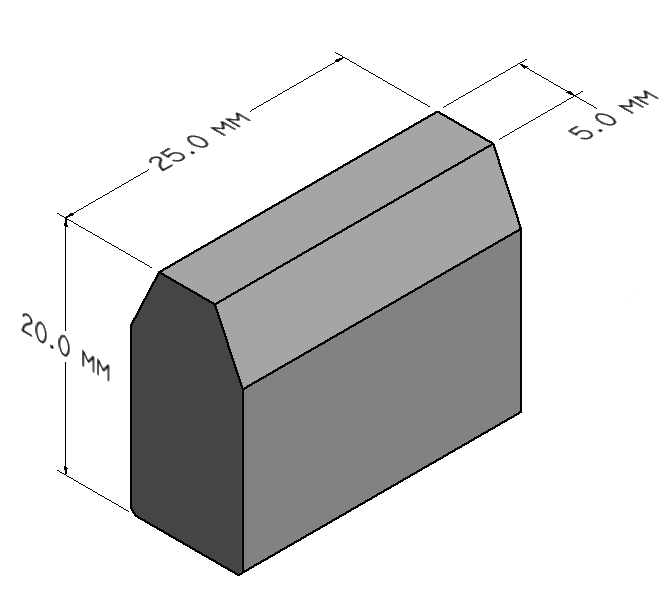
Fig. 15.9 Small Plane Strain Anvils - DSI# 9105-252
| Part Number | Description | Sold As |
|---|---|---|
| Small Plane Strain Anvils | ||
| 9105-252 | Small Plane Strain Anvil - Tungsten Carbide - 5 x 25 x 20 mm (0.196 x 0.984 x 0.787 in) | Pack of 10 |
| 9105-352 | Small Plane Strain Anvil - Tungsten Carbide - 5 x 35 x 20 mm (0.196 x 1.377 x 0.787 in) | Pack of 10 |
| Anvils For High-Temperature Studies | ||
| 9105-256 | Small Plane Strain Anvil - Pure Tungsten - 5 x 25 x 20 mm (0.196 x 0.984 x 0.787 in) | Ea. |
15.3.2. Large Plane Strain
Large Plane Strain Anvil Assemblies use 10 x 42 x 20 mm (0.393 x 1.653 x 0.787 in) anvils.
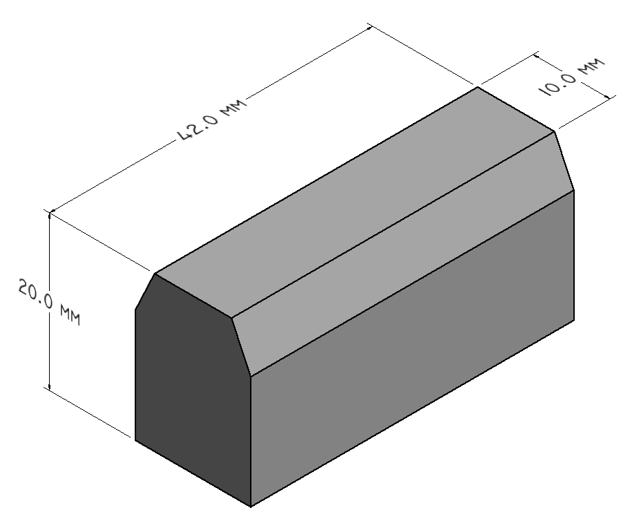
Fig. 15.10 Large Plane Strain Anvils - DSI# 9110-422
| Part Number | Description | Sold As |
|---|---|---|
| 9110-422 | Large Plane Strain Anvil - Tungsten Carbide - Straight Sides - 10 x 42 x 20 mm (0.393 x 1.653 x 0.787 in) | Pack of 2 |
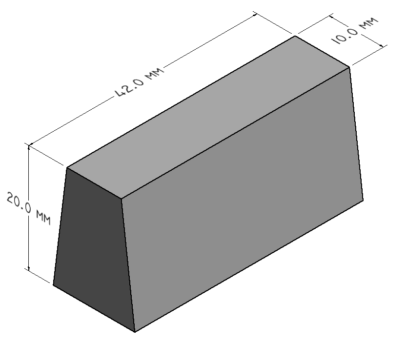
Fig. 15.11 Plane Strain Anvils - DSI# 9110-432.
| Part Number | Description | Sold As |
|---|---|---|
| 9110-432 | Large Plane Strain Anvil - Tungsten Carbide - Tapered Sides - 10 x 42 x 20 mm (0.393 x 1.653 x 0.787 in) with | Pack of 2 |
15.3.3. MAXStrain
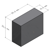
Fig. 15.12 MAXStrain Anvils - DSI# 9110-252.
| Part Number | Description | Sold As |
|---|---|---|
| 9110-252 | MAXStrain - Punch-Style Plane Strain Anvil - Tungsten Carbide - 10 x 25 x 20 mm (0.393 x 0.984 x 0.787 in) | Pack of 10 |
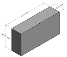
Fig. 15.13 MAXStrain Anvils - DSI# 9110-402.
| Part Number | Description | Sold As |
|---|---|---|
| 9110-402 | MAXStrain - Punch-Style Plane Strain Anvil - Tungsten Carbide - 10 x 40 x 20 mm (0.393 x 1.574 x 0.787 in) | Pack of 2 |
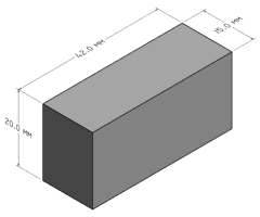
Fig. 15.14 MAXStrain Anvils - DSI# 9115-422.
| Part Number | Description | Sold As |
|---|---|---|
| 9115-422 | MAXStrain - Punch-Style Plane Strain Anvil - Tungsten Carbide - 15 x 42 x 20 mm (0.590 x 1.653 x 0.787 in) | Pack of 2 |
15.4. Plane Strain Anvil Alignment Tool
Alignment of the Plane Strain Anvils is crucial to a successful simulation. The Plane Strain Anvil Alignment Tool provides the ability to properly position the anvils, relative to each other, while protecting the operator from hazardous pinch points.
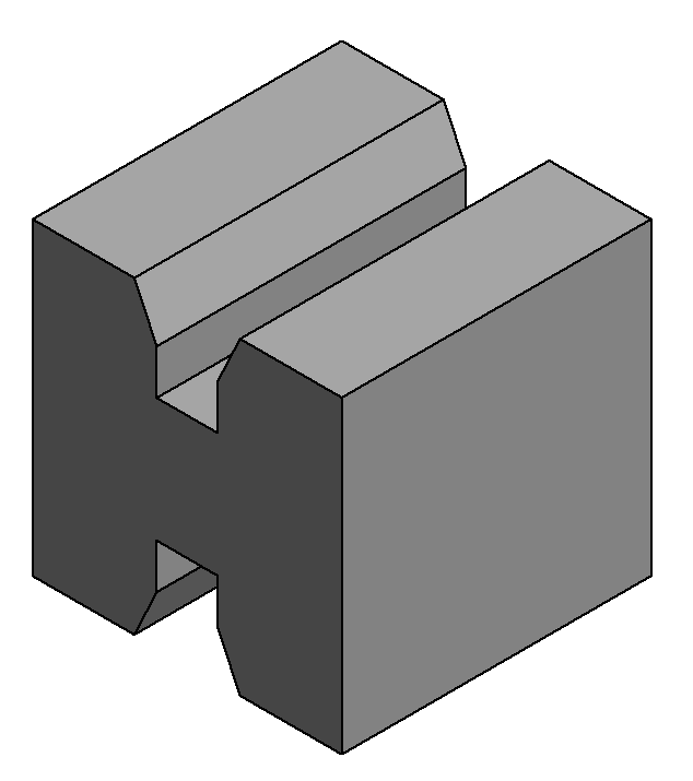
Fig. 15.15 Plane Strain Anvil Alignment Tool - DSI# GN2885K
| Part Number | Description | Sold As |
|---|---|---|
| MAXStrain | ||
| 3M131 | Anvil Base Alignment Tool | Ea. |
| 3M963 | Specialized Tools and Fixtures Kit - MaxStrain II | Ea. |
| All Other Plane Strain Fixtures | ||
| 9565-900 | Alignment Fixture - 10 mm Plane Strain Anvil | Ea. |
| GN2885K | Alignment Fixture - 5 mm Plane Strain Anvil | Ea. |
15.5. Specimen Loading Tools and Clips
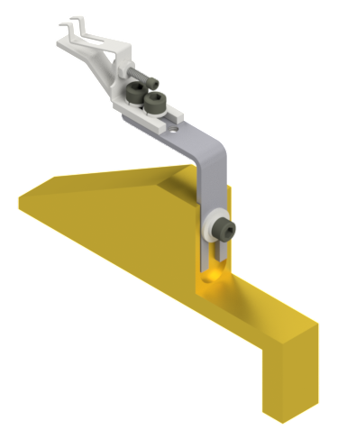
Fig. 15.16 Specimen Loading Tool
For more information on Specimen Loading Tools and Clips can be found here.
15.6. Plane Strain Compression Testing Consumables Kits
Plane Strain consumable kits contain many of the most commonly used consumables for differing Plane Strain testing methodologies.
15.6.1. Hot Compression Starter Kit - DSI# 9570-000
Kit 9570-000 contains the following parts:
| Part Number | Description |
|---|---|
| RMX005SB | 5 mil thick Graphite Foil |
| RMX004S | 4 mil thick Tantalum Sheet |
| RMX010SA | 10 mil thick Graphite Foil |
| HW008 | Super Bonder Glue |
| HW008A | Omega Bond Thermocouple Cement |
| HW014 | Anti-seize Compound - Nickel Paste |
| HW510 | Superlube |
15.6.2. Small Plane Strain Compression Kit - DSI# 9570-002
Kit 9570-002 contains the following parts:
| Part Number | Description |
|---|---|
| 9105-252 | Small Plane Strain Anvil - Tungsten Carbide - 5 x 25 x 10 mm (0.196 x 0.984 x 0.393 in) |
| 9560-303 | Backing Block - Small Plane Strain |
| 9560-304 | Side Conductor Plate - Small Plane Strain |
| 9560-305 | Bottom Conductor Plate - Small Plane Strain |
15.6.3. Large Plane Strain Compression Kit - DSI# 9570-003
Kit 9570-003 contains the following parts:
| Part Number | Description |
|---|---|
| 9110-422 | Large Plane Strain Anvil - Tungsten Carbide - Straight Sides - 10 x 42 x 15 mm (0.393 x 1.653 x 0.59 in) |
| 9565-304 | Backing Block - Large Plane Strain |
| 9565-306 | Side Conductor Plate - Large Plane Strain |
| 9565-307 | Bottom Conductor Plate - Large Plane Strain |
For additional consumable items see Gleeble Consumables.